Cleaning device for steel member shot blasting

A cleaning device and a technology for steel components, which are applied to used abrasive treatment devices, cleaning methods using liquids, cleaning methods using tools, etc. The cleaning effect is not ideal and other problems, so as to reduce the probability of damaging the surface of steel components, clean comprehensively and neatly, and improve the effect of scraping.

Pending Publication Date: 2022-03-25
重庆信晶机电有限公司
View PDF10 Cites 0 Cited by
  • Summary
  • Abstract
  • Description
  • Claims
  • Application Information

AI Technical Summary

Problems solved by technology

[0006] A scraper is provided at the lower end of the lifting plate in the prior art, because the residue on the surface of the steel component is scraped off, but when the steel component is transported by the conveyor, since the scraper itself is in a fixed state, it is necessary to scrape off the steel component. When the surface of the component is scratched, there will be many scratches on the surface, which will cause the overall appearance of the steel component to be unattractive, resulting in problems such as low quality of the steel component, and after the steel component is scraped off, the residue on the surface needs to be cleaned by water flow. The existing water flow will be in a static state during cleaning, and the same surface can only be washed once, and the water flow is in a vertical state, and there will be consequences that the residual value of the surface cannot be washed completely, so the cleaning effect of the equipment is not ideal. , the invention provides a cleaning device for shot blasting of steel components

Method used


Image

  • Cleaning device for steel member shot blasting
  • Cleaning device for steel member shot blasting
  • Cleaning device for steel member shot blasting

Examples


Embodiment

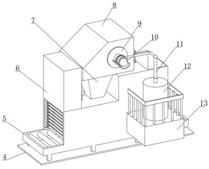
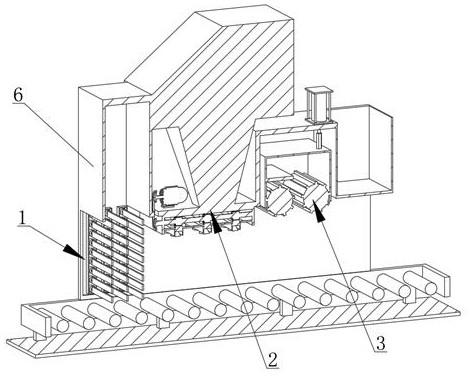
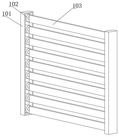
[0032] like Figures 1 to 7 As shown, a cleaning device for shot blasting of steel components includes a base plate 4, a conveyor 5 is fixedly installed on the upper surface of the base plate 4, and the upper surface of the conveyor 5 is fixedly connected with a cabinet 6, and one end of the cabinet 6 is set as an inlet and another One end is set as an outlet, and the inner wall of the cabinet 6 is sequentially installed with a scraper assembly 1, a cleaning assembly 2, and a cleaning assembly 3 from the outlet. The cleaning assembly 2 includes an installation box 204, a first motor 201, two third gears 212, and a nozzle 211. The installation box 204 is fixedly connected to the inner wall of the cabinet 6, the upper surface of the cabinet 6 is fixedly installed with the first motor 201, the output shaft of the first motor 201 is fixedly connected with the third gear 212, and the end of the other third gear 212 is fixedly connected There is a second rotating shaft 208, two thir...


PUM


Abstract

The invention relates to the technical field of steel member shot blasting, in particular to a steel member shot blasting cleaning device which comprises a bottom plate, a conveyor is fixedly mounted on the upper surface of the bottom plate, a case is fixedly connected to the upper surface of the conveyor, an inlet is formed in one end of the case, and an outlet is formed in the other end of the case. A scraping plate assembly, a cleaning assembly and a sweeping assembly are sequentially installed on the inner wall of the machine box from an outlet, the cleaning assembly comprises an installation box, a first motor, two third gears and a spray head, an output shaft of the first motor is fixedly connected with the third gears, and the end of the other third gear is fixedly connected with a second rotating shaft; two third gears are connected with a first belt, water flow is made to have flowability, residues existing on the surface can be flushed down, a good foundation is provided for subsequent sweeping, and the equipment can sweep more comprehensively and neatly in the communicated sweeping time.

Description

technical field [0001] The invention relates to the technical field of shot blasting of steel components, in particular to a cleaning device for shot blasting of steel components. Background technique [0002] Due to its unique advantages in three aspects of "height, large and light", steel components are widely used in the field of construction engineering, and are indispensable and important parts for modern engineering construction. Before the steel component is used, it is necessary to remove the cutting slag on the cutting edge of the cut steel component or the scale formed on the cutting surface by the shot blasting machine, so as to achieve the effect of convenient use and beautiful appearance. [0003] After searching, for example, the application number is CN201821331662.7, a cleaning device for steel component shot blasting, including a workbench and a frame, characterized in that the workbench is located at the bottom of the frame, and the top end of the guide rod...

Claims


Application Information

Patent Timeline
IPC IPC(8): B08B1/02B08B3/02B24C9/00B08B13/00
CPCB08B3/022B08B3/024B24C9/00B08B13/00B08B1/165B08B1/20
Inventor 何敏郑德群李燕
Owner 重庆信晶机电有限公司
Why Eureka
Try Eureka