Bailey bracket of cast-in-place box girder and construction method of Bailey bracket
A technology of cast-in-place boxes and support rods, applied in bridges, bridge construction, erection/assembly of bridges, etc., can solve problems such as low safety factor and insufficient support strength, achieve strong connection stability, improve support effect, and increase support strength Effect
- Summary
- Abstract
- Description
- Claims
- Application Information
AI Technical Summary
Problems solved by technology
Method used
Image

Examples
Embodiment 1
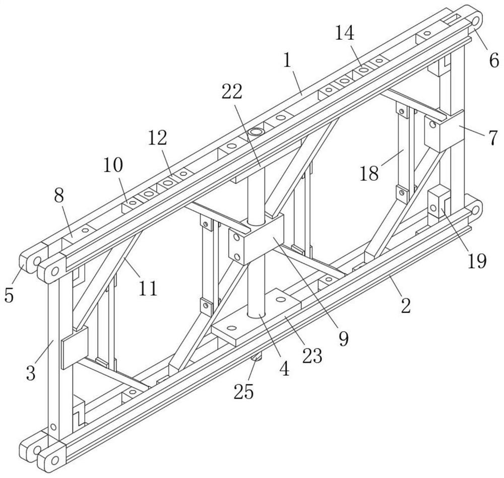
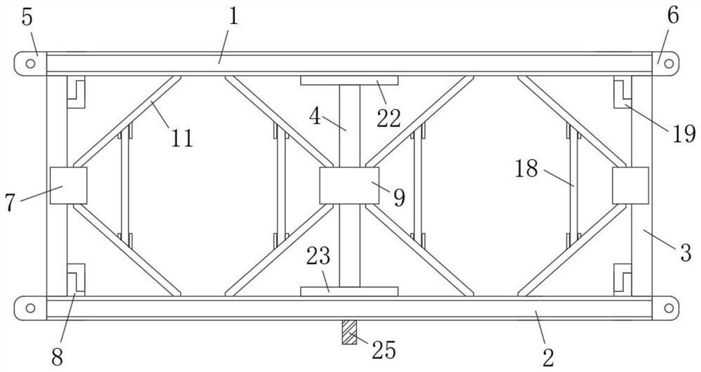
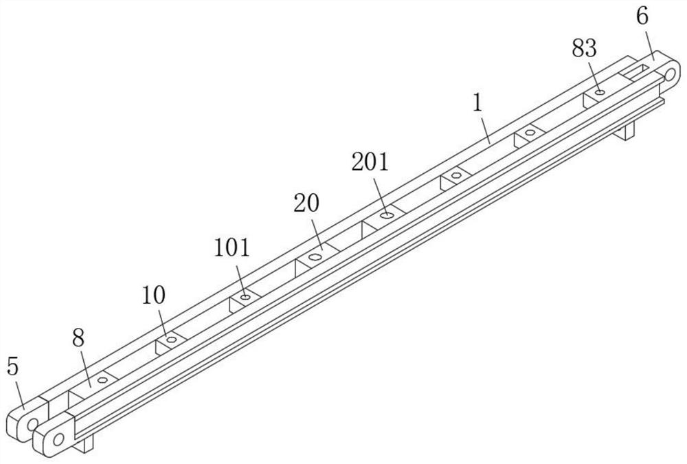
[0055] refer to Figure 1-12 , a Bailey support for cast-in-place box girders, including an upper chord 1 and a lower chord 2, two vertical rods 3 are symmetrically arranged between the upper chord 1 and the lower chord 2, and the two ends of the upper chord 1 and the lower chord 2 are A female head 5 and a male head 6 for docking are provided respectively, a fixed block 7 is fixedly welded on the sides of the two vertical bars 3 close to each other, and the same support bar 4 is fixedly connected between the upper chord 1 and the lower chord 2 , And the support bar 4 is located between the two vertical bars 3, one side of the support bar 4 is rotatably provided with a fixed ring 9, the top and bottom of the two fixed blocks 7 and the top and bottom sides of the fixed ring 9 are all fixed. Diagonal struts 11 are connected, and the tops of the upper diagonal struts 11 are fixedly connected with the upper chord 1 , and the bottom ends of the lower diagonal struts 11 are all fixe...
Embodiment 2
[0062] This embodiment is as a further improvement of the previous embodiment: refer to Figure 1-12 , a Bailey support for cast-in-place box girders, including an upper chord 1 and a lower chord 2, two vertical rods 3 are symmetrically arranged between the upper chord 1 and the lower chord 2, and the two ends of the upper chord 1 and the lower chord 2 are A female head 5 and a male head 6 for docking are provided respectively, a fixed block 7 is fixedly welded on the sides of the two vertical bars 3 close to each other, and the same support bar 4 is fixedly connected between the upper chord 1 and the lower chord 2 , And the support bar 4 is located between the two vertical bars 3, one side of the support bar 4 is rotatably provided with a fixed ring 9, the top and bottom of the two fixed blocks 7 and the top and bottom sides of the fixed ring 9 are all fixed. Diagonal struts 11 are connected, and the tops of the multiple diagonal struts 11 located above are all fixedly connec...
PUM
 Abstract
Description
Claims
Application Information
 - Generate Ideas
- Intellectual Property
- Life Sciences
- Materials
- Tech Scout
- Unparalleled Data Quality
- Higher Quality Content
- 60% Fewer Hallucinations
Browse by: Latest US Patents, China's latest patents, Technical Efficacy Thesaurus, Application Domain, Technology Topic, Popular Technical Reports.
© 2025 PatSnap. All rights reserved.Legal|Privacy policy|Modern Slavery Act Transparency Statement|Sitemap|About US| Contact US: help@patsnap.com