Angular contact self-aligning roller bearing

A self-aligning roller bearing and angular contact technology, used in rolling contact bearings, bearings, bearing components, etc., can solve the problems of bearing failure, single-row rolling element bearing, small axial load, etc., and achieve the effect of improving bearing capacity

Pending Publication Date: 2022-03-25
郭宏军
View PDF0 Cites 0 Cited by
  • Summary
  • Abstract
  • Description
  • Claims
  • Application Information

AI Technical Summary

Problems solved by technology

[0005] Self-aligning roller bearings can not only withstand large radial loads, but also have a good self-aligning function; however, double-row self-aligning roller bearings can only withstand relatively high press

Method used


Image

  • Angular contact self-aligning roller bearing
  • Angular contact self-aligning roller bearing
  • Angular contact self-aligning roller bearing

Examples


Embodiment 1

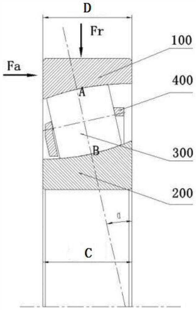
[0044] refer to Figure 1-Figure 4 and Figure 9-Figure 10 , as a preferred embodiment, Embodiment 1 of this embodiment provides an angular contact spherical roller bearing. Embodiment 1 further includes the following technical features:

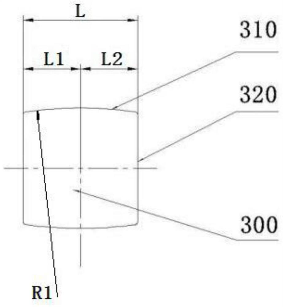
[0045] Taking the axial length of the roller 300 as L, the distance from the center of the first arc to the first axial end of the roller 300 is L1, and the distance from the center of the first arc to the second end of the roller 300 in the axial direction The distance is L2, L1=L2=L / 2. The normal of the outer raceway 110 at point A passes through point B, and the normal of the inner raceway 210 at point B passes through point A. That is, α=β, the forces exerted by the inner raceway 210 and the outer raceway 110 on the roller 300 are collinear and opposite in direction, and these two forces can cancel each other out (gravity is ignored), so there is no need to set up additional limiting structures (such as Rib) limits the roller 300, an...

Embodiment 2

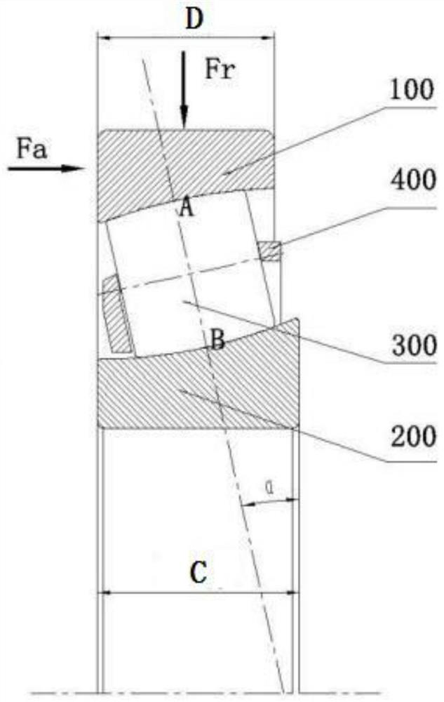
[0049] refer to Figure 5-Figure 8 and Figure 9-Figure 10 , as yet another preferred embodiment, Embodiment 2 of this embodiment provides an angular contact spherical roller bearing. Embodiment 2 further includes the following technical features:

[0050] Taking the axial length of the roller 300 as L, the distance from the center of the first arc to the first axial end of the roller 300 is L1, and the distance from the center of the first arc to the second end of the roller 300 in the axial direction The distance is L2, then L1>L / 2>L2. β<α, that is, the forces exerted by the inner raceway 210 and the outer raceway 110 on the roller 300 are not collinear, and the two cannot cancel (ignoring gravity). A rib is provided on the inner ring 200 , and the rib contacts with the second axial end of the roller 300 to balance the resultant force exerted by the inner raceway 210 and the outer raceway 110 on the roller 300 . When in use, the roller 300 is always in contact with the r...


PUM


Abstract

The invention discloses an angular contact self-aligning roller bearing. The angular contact self-aligning roller bearing comprises a roller, an inner ring, a retainer and an outer ring, the outer raceway is an inner spherical surface, and the sphere center of the inner spherical surface is on the axis of the outer ring and deviates from the central point of the outer ring; the rollers are arranged in a single row, the side surfaces of the rollers are convex curved surfaces, and the convex curved surfaces are formed by taking the first arc as a generatrix and the axes of the rollers as rotating shafts; the inner raceway is a concave curved surface which is formed by taking the second arc as a generatrix and the axis of the inner ring as a rotating shaft; the nominal contact angle of the outer raceway is alpha, the nominal contact angle of the inner raceway is beta, alpha is more than 0 degree and less than 45 degrees, and beta is more than 0 degree and less than 45 degrees; the radius of the inner spherical surface is SR, the radius of the first arc is R1, the radius of the second arc is R2, R1 is larger than or equal to 0.97 SR and smaller than SR, and R1 is larger than or equal to 0.97 R2 and smaller than R2. The angular contact self-aligning roller bearing disclosed by the invention not only can bear axial and radial independent loads and combined loads, but also can adapt to the condition that a bearing mounting hole is not aligned with a shaft.

Description

technical field [0001] The invention relates to the technical field of radial rolling bearings, in particular to an angular contact spherical roller bearing. Background technique [0002] In line with the development requirements of environmental protection and energy saving in the machinery industry, bearings must be lightweight designed, that is, they can bear greater loads under the same external dimensions, or have smaller dimensions under the same loads. Moreover, in most of the radial bearing applications, the combined load requirements are put forward for the bearings, which mainly bear radial loads and supplemented by axial loads. In addition, due to the limitation of the capacity and precision of the processing equipment, the bearing mounting holes are misaligned, requiring the bearing to have a certain self-aligning performance. However, the bearings currently on the market cannot take into account the above three points. [0003] The rolling elements of the exis...

Claims


Application Information

Patent Timeline
IPC IPC(8): F16C23/08F16C33/58F16C33/36
CPCF16C23/084F16C33/58F16C33/585F16C33/36F16C23/086F16C19/36F16C2240/76F16C23/08F16C33/583
Inventor 郭宏军程凯
Owner 郭宏军
Why Eureka
Try Eureka