
Pressure sensor calibration method and device and electronic equipment

A pressure sensor and calibration method technology, applied in the field of sensor calibration, can solve problems such as low calibration accuracy, inability to ensure accuracy, and difficult calibration process, and achieve the effect of improving calibration accuracy

Pending Publication Date: 2022-03-25
南京英锐创电子科技有限公司
View PDF12 Cites 2 Cited by
  • Summary
  • Abstract
  • Description
  • Claims
  • Application Information

AI Technical Summary

Problems solved by technology

Among them, the single-temperature calibration method is easy to implement because there is no temperature change, but the accuracy of the entire temperature range is low. Because there is no compensation coefficient for temperature, the final output accuracy of the pressure sensor depends entirely on MEMS (full name MicroElectromechanical System, that is, Micro Electromechanical System). The temperature characteristics of the electromechanical system), while the commonly used piezoresistive MEMS characteristics drift greatly with temperature, and finally the single-temperature calibration accuracy is low in the production stage
Furthermore, multi-temperature calibration has temperature changes. Although the calibration accuracy in the entire temperature zone is high, the calibration process is difficult, mainly due to the difficulty of temperature control during the calibration process, and the calibration also has very high requirements for the stability of the temperature control equipment. As a result, not only the calibration accuracy cannot be ensured, but also the production cost is high
[0003] Overall, the existing calibration methods for pressure sensors still have low calibration accuracy.

Method used


Image

  • Pressure sensor calibration method and device and electronic equipment
  • Pressure sensor calibration method and device and electronic equipment
  • Pressure sensor calibration method and device and electronic equipment

Examples


Embodiment 1

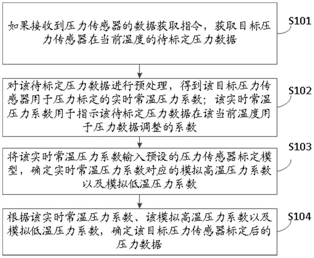
[0029] figure 1 It is a schematic flowchart of a calibration method for a pressure sensor provided in an embodiment of the present invention. figure 1 As seen, the method includes the following steps:

[0030] Step S101: If a data acquisition instruction of a pressure sensor is received, acquire the pressure data to be calibrated of the target pressure sensor at the current temperature.

[0031] In this embodiment, the current temperature is normal temperature, and the temperature range of the normal temperature is: 25°-30°. Then, through the ADC output terminal of the target pressure sensor, the pressure data to be calibrated at the current temperature of the target pressure sensor is obtained.

[0032] Step S102: Preprocessing the pressure data to be calibrated to obtain the real-time normal temperature pressure coefficient of the target pressure sensor for pressure calibration; the real-time normal temperature pressure coefficient is used to indicate that the pressure dat...

Embodiment 2

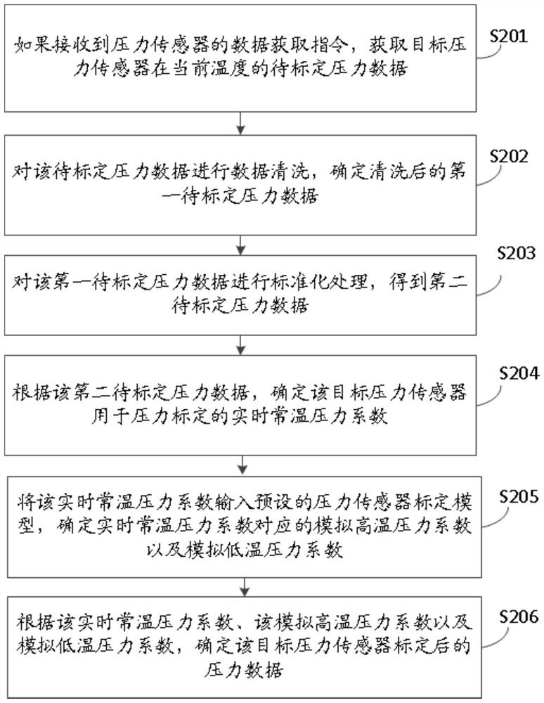
[0039] exist figure 1 On the basis of the schematic flowchart of a calibration method for a pressure sensor shown, this embodiment also provides another calibration method for a pressure sensor. figure 2 It is a schematic flowchart of another pressure sensor calibration method provided by the embodiment of the present invention. The method includes:

[0040] Step S201: If a data acquisition instruction of a pressure sensor is received, acquire the pressure data to be calibrated of the target pressure sensor at the current temperature.

[0041] Step S202: Perform data cleaning on the pressure data to be calibrated, and determine the first pressure data to be calibrated after cleaning.

[0042] In this embodiment, firstly, according to the pressure data, the pressure data to be calibrated beyond the preset analog-to-digital conversion range is determined. Then, delete the pressure data to be calibrated beyond the preset analog-to-digital conversion range, and determine the f...

Embodiment 3

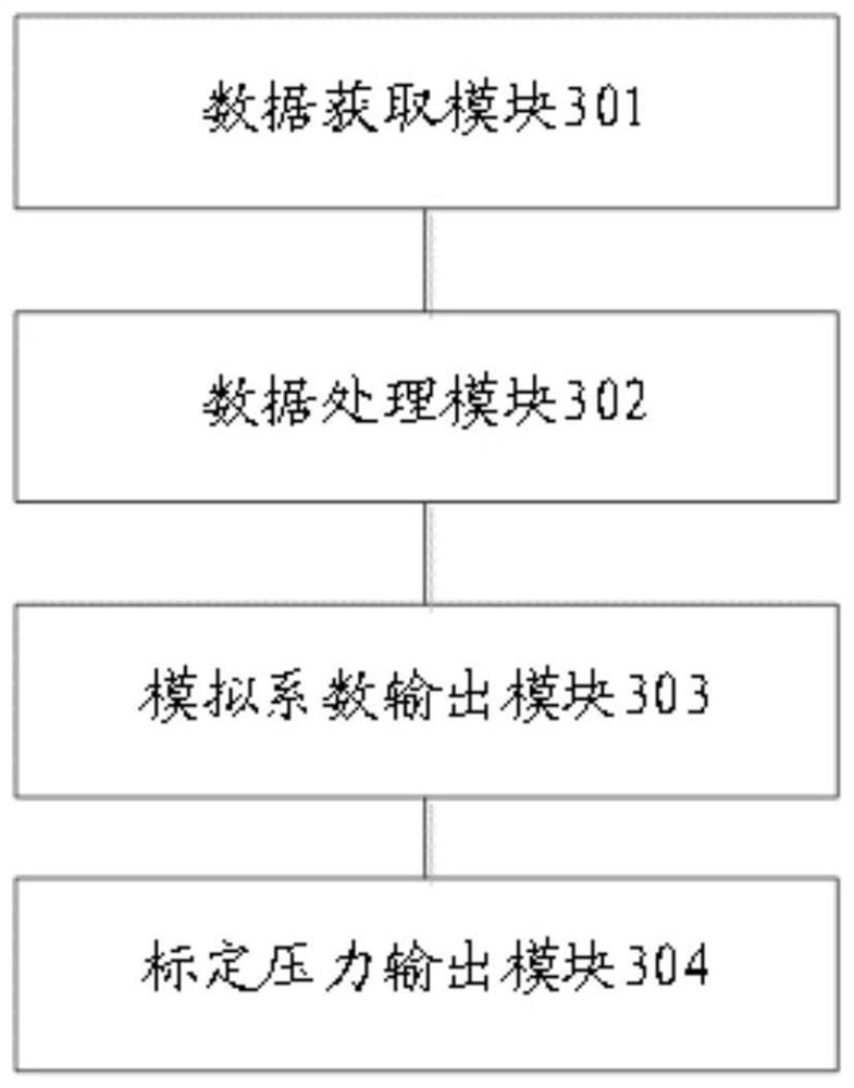
[0082] The embodiment of the invention also provides a calibration device for the pressure sensor. Such as image 3 as shown, image 3 A schematic structural diagram of a pressure sensor calibration device provided in an embodiment of the present invention, the device includes:

[0083] The data acquisition module 301 is configured to acquire the pressure data to be calibrated of the target pressure sensor at the current temperature if a data acquisition instruction from the pressure sensor is received.

[0084] The data processing module 302 is used to preprocess the pressure data to be calibrated to obtain the real-time normal temperature pressure coefficient of the target pressure sensor used for pressure calibration; Coefficient to adjust for pressure data.

[0085] The simulation coefficient output module 303 is configured to input the real-time normal-temperature pressure coefficient into the preset pressure sensor calibration model, and determine the simulated high-t...


PUM


Abstract

The invention provides a pressure sensor calibration method and device and electronic equipment, and the method comprises the steps: obtaining the to-be-calibrated pressure data of a target pressure sensor at the current temperature if a data obtaining instruction of the pressure sensor is received; preprocessing the to-be-calibrated pressure data to obtain a real-time normal-temperature pressure coefficient of the target pressure sensor for pressure calibration; inputting the real-time normal-temperature pressure coefficient into a preset pressure sensor calibration model, and determining a simulated high-temperature pressure coefficient and a simulated low-temperature pressure coefficient corresponding to the real-time normal-temperature pressure coefficient; and determining calibrated pressure data of the target pressure sensor according to the real-time normal-temperature pressure coefficient, the simulated high-temperature pressure coefficient and the simulated low-temperature pressure coefficient. According to the method, pressure calibration is realized through the full-temperature-zone pressure adjustment coefficient, so that the calibration precision of the pressure sensor is improved.

Description

technical field [0001] The invention relates to the technical field of sensor calibration, in particular to a pressure sensor calibration method, device and electronic equipment. Background technique [0002] Due to the temperature drift characteristics of the sensor, the existing common calibration methods include single temperature calibration and multi-temperature calibration. Among them, the single-temperature calibration method is easy to implement because there is no temperature change, but the accuracy of the entire temperature range is low. Because there is no compensation coefficient for temperature, the final output accuracy of the pressure sensor depends entirely on MEMS (full name MicroElectromechanical System, that is, Micro Electromechanical System). The temperature characteristics of the electromechanical system), while the currently commonly used piezoresistive MEMS characteristics have a large drift with temperature, and finally the single-temperature calibr...

Claims


Application Information

Patent Timeline
IPC IPC(8): G01L27/00
CPCG01L27/005
Inventor 张军温立
Owner 南京英锐创电子科技有限公司
Learn More