
Large-current electric tool switch

A power tool and high-current technology, which is applied to electric switches, flip switches/rocker switch components, circuits, etc., can solve the problem of temperature rise of switches, shortened service life, difficult to solve the problem of fast on-off of switches and dynamic and static contacts Anti-bounce, anti-arc and other issues to achieve the effect of reducing temperature rise and reducing local heating

Pending Publication Date: 2022-03-25
NINGBO CPX ELECTRONICS TECH
View PDF0 Cites 0 Cited by
  • Summary
  • Abstract
  • Description
  • Claims
  • Application Information

AI Technical Summary

Problems solved by technology

[0002] As the power demand of complete tools in the market is getting higher and higher, the current-carrying requirements for electric tool switches are also getting higher and higher. At present, electric tool switches are commonly used, due to current-carrying structure design and local heating and temperature rise. Adaptive current application is somewhat limited
One is that the main switch structure design of the existing electric tool switch is mainly a tension spring structure and a bullet structure. The contact parts of the corresponding bracket terminals and conductive bridges are all formed by stamping process, resulting in the switch being closed or the switch being disconnected. During the process, it is easy to generate local concentrated heat in the contact area between the bracket terminal and the conductive bridge, and the temperature rise of the switch is too high. Problems such as anti-bounce and anti-arcing make the contacts easier to ablate, stick and generate high temperature under the same power, and reduce the reliability of work and shorten the service life; the third is the reversing of the existing electric tool switch components, when a large current is applied and the reversing component is used as a current switch, the reversing component cannot be rotated and positioned effectively and quickly, resulting in easy arc ignition between the reversing tab and the motor terminal when the reversing component is used as a switch , which in turn leads to failure of the reversing component due to heating, melting, deformation; fourth, in the reversing component of the existing electric tool switch, the motor terminals are easily affected by shock and vibration during use and loosen, which will also cause the reversing component to generate arcs during use. and heating and melting deformation failure
At the same time, in addition to the above four main defects in use, the existing structure also has disadvantages such as complex assembly process, not easy to realize automatic production and relatively high cost.

Method used


Image

  • Large-current electric tool switch
  • Large-current electric tool switch
  • Large-current electric tool switch

Examples


Embodiment Construction

[0044] The embodiments of the present invention will be further described in detail according to the above-mentioned drawings.

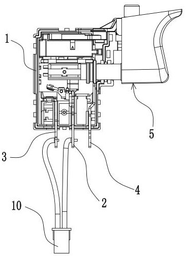
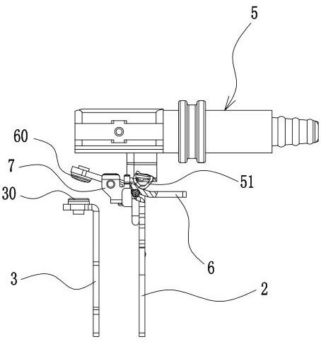
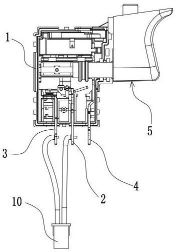
[0045] Such as Figure 1~Figure 28 As shown, 1. Shell, 10. Connector assembly, 11. Bottom shell, 111. Buckle groove, 12. Shell cover, 13. Spring, 14. Conductive rod, 2. Bracket terminal, 21. Positioning tongue, 211 .Positioning column, 212. Positioning gap, 22. Connection gap, 23. Connection hole, 24. Connection pin, 25. Mounting groove, 26. Anti-loose convex shell, 3. Static contact piece terminal, 30. Static contact, 4. Positive pole terminal, 5. Trigger assembly, 51. Warhead, 52. Push rod, 521. End hole, 522. Side hole, 53. Dustproof ring, 54. Trigger block, 55. Locating pin, 56. Push rod spring , 57. Bullet spring, 6. Conductive bridge, 60. Moving contact, 61. Arc groove, 62. Quick on-off protrusion, 621. First shift point, 622. Second shift point, 63. Limiting slot, 64. Chamfer slope, 7. Elastic seat, 71. Bottom plate, 711. Positioning hole, 7...


PUM


Abstract

The invention discloses a high-current electric tool switch, which structurally comprises a shell, a bracket terminal, a static contact piece terminal, a positive terminal, a reversing assembly, a trigger assembly, a conductive bridge, a reversing rod and the like, and is mainly characterized in that the conductive bridge is rotationally assembled on a conductive rod through arc contact; meanwhile, a quick on-off bulge is additionally arranged on the outer surface of the middle part of the conductive bridge, and elastic seats are arranged on the two sides of the conductive bridge for structural matching, so that quick on-off, rebound prevention and arc discharge prevention between the conductive bridge and the static contact piece terminal are realized; besides, reciprocating rotation of the reversing rod driving the reversing turntable in the reversing bottom shell is doubly positioned, so that looseness of the motor terminal caused by impact and vibration in actual use can be reduced, and the situations of arc ignition, heating melting deformation failure and the like during use of the reversing assembly can be avoided. Therefore, the use reliability of the large-current electric tool switch is better ensured, and the service life is prolonged.

Description

technical field [0001] The invention relates to an electric tool switch, in particular to a high-current electric tool switch. Background technique [0002] As the power demand of complete tools in the market is getting higher and higher, the current-carrying requirements for electric tool switches are also getting higher and higher. At present, electric tool switches are commonly used, due to current-carrying structure design and local heating and temperature rise. Adaptive current applications are limited. One is that the main switch structure design of the existing electric tool switch is mainly a tension spring structure and a bullet structure. The contact parts of the corresponding bracket terminals and conductive bridges are all formed by stamping process, resulting in the switch being closed or the switch being disconnected. During the process, it is easy to generate local concentrated heat in the contact area between the bracket terminal and the conductive bridge, a...

Claims


Application Information

Patent Timeline
Patent Type & Authority Applications(China)
IPC IPC(8): H01H23/20H01H23/12H01H23/02H01H1/58H01H1/50
CPCH01H23/20H01H23/12H01H23/02H01H1/58H01H1/50
Inventor 谭和平
Owner NINGBO CPX ELECTRONICS TECH
Learn More