Lighting device for flush underground lighting

An embedded and illuminator technology, applied in lighting devices, lighting applications, aircraft lighting devices, etc., can solve problems such as low energy efficiency, achieve low cost, improve load transfer, and simplify maintenance work

Inactive Publication Date: 2003-03-26
ADB
View PDF0 Cites 0 Cited by
  • Summary
  • Abstract
  • Description
  • Claims
  • Application Information

AI Technical Summary

Problems solved by technology

Furthermore, this form of lighting is only relatively energy-efficient, since only a relatively small fraction of the light produced by the overall lighting is emitted in the desired color

Method used


Image

  • Lighting device for flush underground lighting
  • Lighting device for flush underground lighting
  • Lighting device for flush underground lighting

Examples


Embodiment Construction

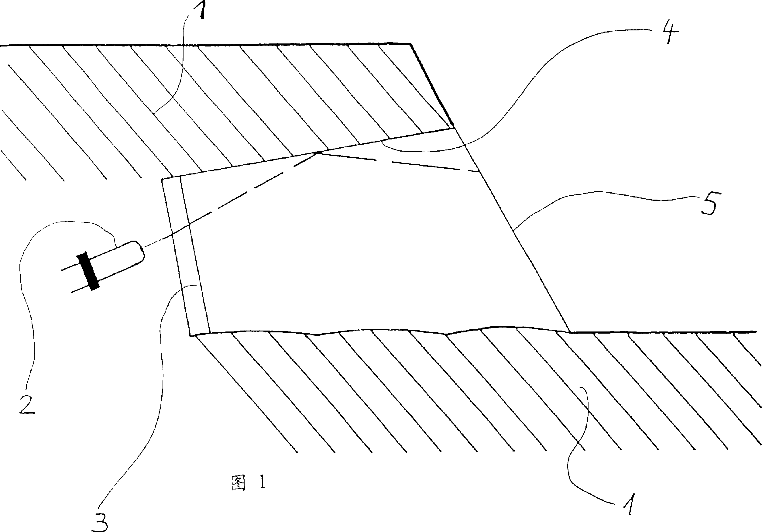
[0024] The recessed underground luminaire of the present invention shown in FIG. 1 has a semiconductor light source 2 installed in the device body or device housing 1 . An optical device 3 is arranged upstream of the semiconductor light source 2 for the generation of light. The light emitted by the semiconductor light source 2 is fully reflected on the total reflection surface 4 before exiting the lighting device through the smooth outer surface 5 .

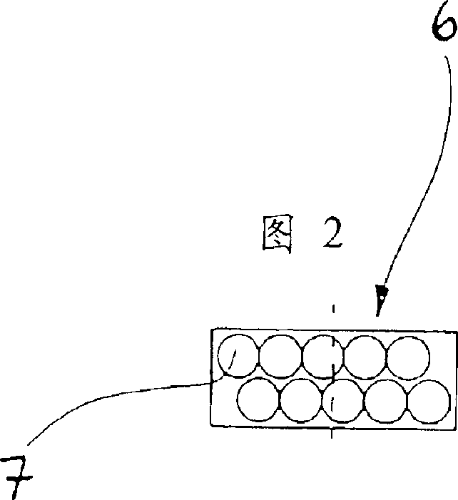
[0025] The semiconductor light source 2 is composed of cluster components 6, and Fig. 2 to Fig. 4 basically show the principle diagram of one of the cluster components. In the exemplary embodiment shown, the semiconductor components 7 belonging to the bundle 6 are arranged next to each other in two rows one above the other. The semiconductor elements 7 in a cluster 6 are mounted on the same element support 8, and the surface on one side of the semiconductor element of this support is formed by a reflective surface 9, so that the...


PUM


Abstract

The invention relates to a lighting device for signalling on and identification and marking of airport traffic areas, e.g. take-off runways, landing runways, taxiways and the like. Said device has light sources (1) for direct emission of visible light. To reduce energy consumption and maintenance costs for said lighting devices, it is proposed that the light sources take the form of semiconductor components.

Description

technical field [0001] The invention relates to a white or other signal colors, such as red, green, blue, yellow embedded underground luminaire. Background technique [0002] Existing underground lighting devices for airports, especially as signs for take-off and landing runways and taxi lanes, usually use incandescent lamps or tungsten-filament halogen lamps as light sources. [0003] When lighting or signaling devices are to emit light with a certain color, which plays an important role especially in airport traffic control, this form of light source has to be combined with optical radiation filters. Since in order to produce color, a certain amount, sometimes a considerable part, of the light emitted by incandescent lamps or tungsten-halogen lamps must be filtered out, so the structure of this type of lighting device should be such that the relatively large amount of unwanted light is produced. The heat is dissipated. Furthermore, lighting devi...

Claims


Application Information

Patent Timeline
Patent Type & Authority Patents(China)
IPC IPC(8): B60Q1/26B60Q7/00B64F1/20E01F9/00E01F9/06E01F9/615F21K99/00F21S2/00F21S8/00F21V5/04F21V29/00F21W111/06H05B37/02
CPCF21Y2113/005F21S8/00E01F9/0165Y02T10/88F21V19/04B60Q2900/20F21V29/004F21V23/04F21W2111/06E01F9/065B64C2027/8236F21V5/04B64F1/20B60Q1/2696F21K99/00B60Q7/00F21Y2101/02B64F1/205B64D2203/00E01F9/559E01F9/617F21S8/022F21S8/032F21S8/083F21V29/85F21Y2113/13F21Y2115/10Y02W30/82
Inventor 米歇尔·范德伦琼-克劳德·范德伍尔德
Owner ADB
Why Eureka
Try Eureka