Stator assembly and motor

A component and stator technology, applied in the direction of electric components, windings, electrical components, etc., can solve the problems of limiting motor performance and uneven distribution of heat generation, and achieve the effect of balancing heat generation and heat dissipation, and reducing loss density

Pending Publication Date: 2022-03-25
上海易唯科电机技术有限公司
View PDF0 Cites 0 Cited by
  • Summary
  • Abstract
  • Description
  • Claims
  • Application Information

AI Technical Summary

Problems solved by technology

At present, no effective improvement measures have been proposed for the uneven distribution of heat generation of the conductors in the slot, and no effective improvement measures have been proposed for the difference in heat dissipation between the inner and outer layers of the conductor in the slot, which limits the further improvement of the motor performance
There are few considerations from the perspective of motor cooling balance effect

Method used


Image

  • Stator assembly and motor
  • Stator assembly and motor
  • Stator assembly and motor

Examples


Embodiment 1

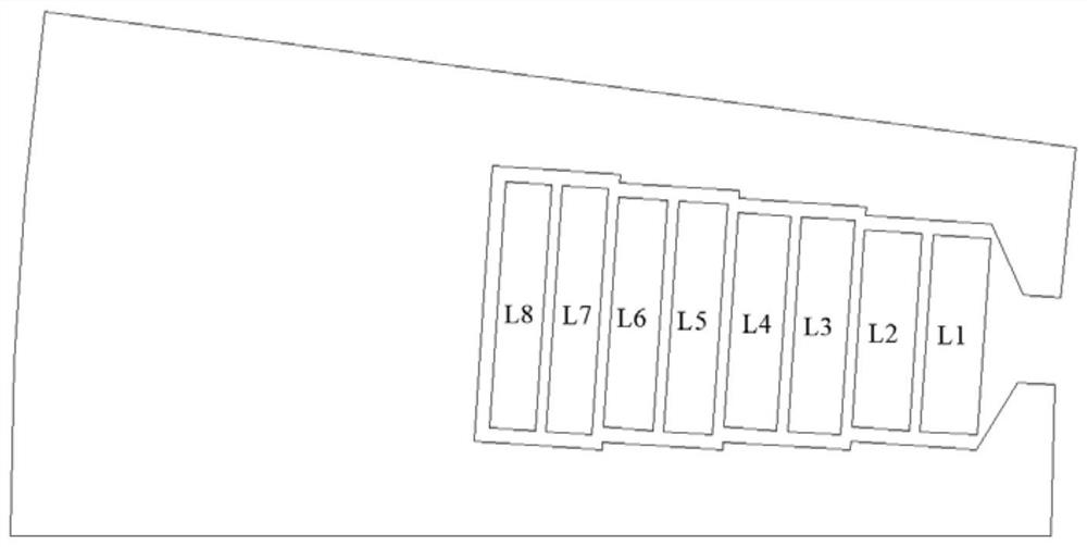
[0059] Such as image 3 As shown, in the technical solution provided by this embodiment, the stator slots are also stepped slots, each stator slot is composed of 4 connected rectangular slots, and each stator slot is provided with 8 layers of rectangular conductors. The rectangular slots of each stator slot are named C1, C2, C3, and C4 in turn. Among them, the rectangular slot C1 is located at the slot opening and belongs to the rectangular slot closest to the center of the iron core in the slot; the rectangular slot C4 is located at the bottom of the slot and belongs to the closest slot in the slot. A rectangular slot in the outer circle of the core. The rectangular conductors in each stator slot are named L1, L2, L3, L4, L5, L6, L7, and L8 in turn, where the L1 conductor is located at the slot opening and belongs to the innermost conductor in the slot near the center of the iron core; the L8 conductor is located at The bottom of the slot belongs to the outermost conductor i...

Embodiment 2

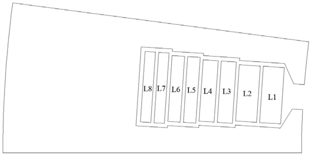
[0066] Such as Figure 5 As shown, in the technical solution provided by this embodiment, the stator slots are also stepped slots, each stator slot is composed of 4 connected rectangular slots, and each stator slot is provided with 8 layers of rectangular conductors. The rectangular slots of each stator slot are named C1, C2, C3, and C4 in turn. Among them, the rectangular slot C1 is located at the slot opening and belongs to the rectangular slot closest to the center of the iron core in the slot; the rectangular slot C4 is located at the bottom of the slot and belongs to the closest slot in the slot. A rectangular slot in the outer circle of the core. The rectangular conductors in the same stator slot are named L1, L2, L3, L4, L5, L6, L7, and L8 in turn. The L1 conductor is located at the slot opening and belongs to the innermost conductor in the slot near the center of the iron core; the L8 conductor is located at The bottom of the slot belongs to the outermost conductor in...

Embodiment 3

[0074] Such as Figure 7As shown, in the technical solution provided by this embodiment, the stator slots are also stepped slots, each stator slot is composed of 4 connected rectangular slots, and each stator slot is provided with 8 layers of rectangular conductors. The rectangular slots of each stator slot are named C1, C2, C3, and C4 in turn. Among them, the rectangular slot C1 is located at the slot opening and belongs to the rectangular slot closest to the center of the iron core in the slot; the rectangular slot C4 is located at the bottom of the slot and belongs to the closest slot in the slot. A rectangular slot in the outer circle of the core. The rectangular conductors in the stator slot are named L1, L2, L3, L4, L5, L6, L7, and L8 in turn. The L1 conductor is located at the slot opening and belongs to the innermost conductor in the slot near the center of the iron core; the L8 conductor is located in the slot Bottom, which belongs to the outermost conductor in the s...


PUM


Abstract

The invention belongs to the technical field of motors, and particularly relates to a stator assembly and a motor. The stator assembly comprises a stator core and a winding. The stator core is provided with a plurality of stator grooves, and the stator grooves are sequentially arranged in the circumferential direction of the stator core and are in an annular array shape. The winding is embedded and wound in the stator groove, and the winding is formed by winding a rectangular conductor; a plurality of layers of rectangular conductors can be installed in each stator groove, and the rectangular conductors are sequentially arranged in the radial direction of the stator iron core. Wherein the sectional area of the rectangular conductor closest to the center of the stator core is larger than the average sectional area of all the rectangular conductors in the stator slots. By increasing the area of the conductor in the slot close to the center of the stator core, the loss density of the conductor is reduced, and heating and heat dissipation of different conductors in the stator slot are balanced, so that the purpose of improving the heat dissipation performance of the motor by reducing the maximum temperature of the motor is achieved.

Description

technical field [0001] The invention belongs to the technical field of motors, in particular to a stator assembly and a motor. Background technique [0002] With the development of the new energy automobile industry becoming more mature, the demand for product cost reduction is becoming more and more urgent. As a key component of the drive system of new energy vehicles, the drive motor accounts for a large cost, and the miniaturization of the motor is an important direction to reduce costs. However, one of the main factors restricting the miniaturization of the motor is the heat generation and heat dissipation of the motor. If the heat generation of the motor can be effectively reduced or the heat dissipation of the motor can be improved, it will help the miniaturization of the motor, thereby achieving the effect of cost reduction. [0003] In terms of reducing the heat generation of the motor, it is common to use low-loss materials to reduce the heat generation, or use fla...

Claims


Application Information

Patent Timeline
IPC IPC(8): H02K1/16H02K1/14H02K3/12H02K3/28H02K3/48H02K3/50
CPCH02K1/165H02K1/146H02K3/12H02K3/28H02K3/48H02K3/50H02K2213/03
Inventor 卢芳友
Owner 上海易唯科电机技术有限公司
Why Eureka
Try Eureka