Dual-mode winding device

A winding device and winding technology, applied in electromechanical devices, manufacturing motor generators, electrical components, etc., can solve the problems of unstable machine structure, disordered arrangement of coils, inability to automatically insert wires, etc., without increasing the radius of gyration, The effect of improving the stress state and increasing the safety of the machine

Inactive Publication Date: 2022-03-25
JIANGSU NIDE AUTOMATION TECH
View PDF0 Cites 0 Cited by
  • Summary
  • Abstract
  • Description
  • Claims
  • Application Information

AI Technical Summary

Problems solved by technology

When the number of parallel windings of the electromagnetic wire is small, the fixed structure of the mold can be used, but when the number of parallel windings is large, the phenomenon of multi-strand wire winding will occur, and the arrangement of the wound coils will be chaotic and irregular, and the resistance of the embedding wire will increase at the same time. , Reduce the quality of the embedded line, and in severe cases, it will also lead to the inability to automatically insert the line
In addition, the force on the head part of the winding device in the prior art is unbalanced, resulting in an unstable machine structure

Method used


Image

  • Dual-mode winding device
  • Dual-mode winding device
  • Dual-mode winding device

Examples


Embodiment Construction

[0033] The following will clearly and completely describe the technical solutions in the embodiments of the present invention with reference to the accompanying drawings in the embodiments of the present invention. Obviously, the described embodiments are only some, not all, embodiments of the present invention. Based on the embodiments of the present invention, all other embodiments obtained by persons of ordinary skill in the art without making creative efforts belong to the protection scope of the present invention.

[0034] In the following description, many specific details are set forth in order to fully understand the present invention, but the present invention can also be implemented in other ways different from those described here, therefore, the protection scope of the present invention is not limited by the specific implementation disclosed below. Example limitations.

[0035] In the description of the present application, it should be understood that the terms "c...


PUM


Abstract

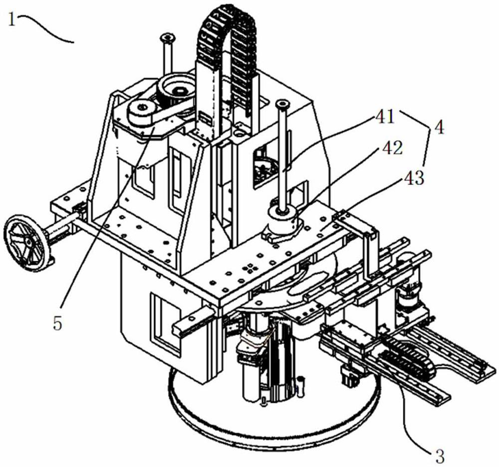
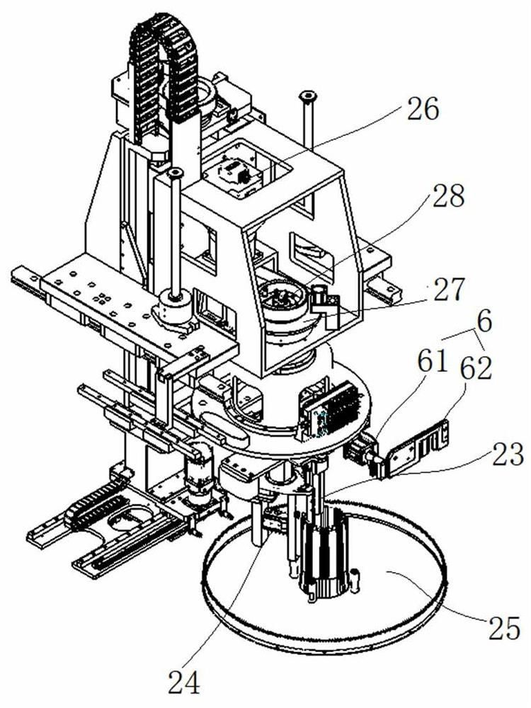
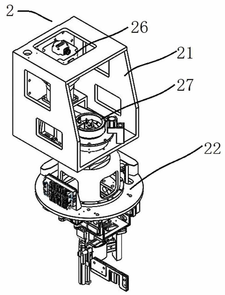
The invention discloses a dual-mode winding device which comprises a winding mechanism, a transfer mechanism, an anti-falling mechanism and a die sinking mechanism. The winding mechanism comprises a winding frame, a winding round seat, a fixed winding mold, a movable winding mold and a wire cup; the transfer mechanism comprises a transfer seat, a transfer guide rail arranged at the bottom of the transfer seat, and a transfer servo and a transfer rack which are arranged on the transfer seat; the anti-falling mechanisms are symmetrically arranged on the two sides of the winding frame. Each anti-falling mechanism comprises a guide rod, a pneumatic chuck and a connecting plate. The die sinking mechanism comprises a die sinking frame, a die sinking servo arranged on the die sinking frame, a lead screw connected with the die sinking servo and a die sinking block connected with the lead screw. The wire winding device is connected with the wire winding mechanism through the transfer mechanism, so that the butt joint center of the fixed wire winding mold and the movable wire winding mold does not deviate; the opening and closing stroke of the winding mold is replaced, the centers of the winding mold and the wire cup are adjusted through the mold adjusting mechanism hand wheel, and finally the varnished wire is wound and formed through the sinking mold.

Description

technical field [0001] The invention relates to the technical field of motor production, in particular to a dual-mode winding device. Background technique [0002] The motor winding is wound by electromagnetic wire. Due to structural reasons, the general winding machine is designed to have a fixed mold, and the cable outlet is installed on the rotating fly fork to rotate around the mold. When the number of parallel windings of the electromagnetic wire is small, the fixed structure of the mold can be used, but when the number of parallel windings is large, the phenomenon of multi-strand wire winding will occur, and the arrangement of the wound coils will be chaotic and irregular, and the resistance of the embedding wire will increase at the same time. , Reduce the quality of the embedding line, and in severe cases, it will also cause the inability to automatically insert the line. In addition, the head part of the winding device in the prior art is unbalanced in force, resul...

Claims


Application Information

Patent Timeline
IPC IPC(8): H02K15/08
CPCH02K15/08
Inventor 张帮伟林启发
Owner JIANGSU NIDE AUTOMATION TECH
Why Eureka
Try Eureka