Flexible fuel oil pipeline for power application of aircraft engine

A technology for aircraft engines and fuel pipes, applied in branch lines, hoses, pipes, etc., can solve problems such as large thermal displacement, gas leakage, safety and reliability of rigid fuel inlet pipes, and impact on service life, and achieve complete machine Effects of improved safety and increased operational reliability

Pending Publication Date: 2017-08-18
SHENYANG RUBBER RES & DESIGN INST CO LTD
View PDF0 Cites 2 Cited by
  • Summary
  • Abstract
  • Description
  • Claims
  • Application Information

AI Technical Summary

Problems solved by technology

Since the ambient temperature and working temperature of the pipeline vary greatly (between -50 and +250°C), the resulting thermal displacement is relatively large, so a large thermal stress is formed, thus affecting the safety and reliability of the rigid oil inlet manifold. and service life are seriously affected
At the same time, in order to adapt to the changing thermal displacement, the metal rigid oil inlet manifold and the penetrating afterburner outer case wall must adopt a movable sealing structure, which will bring the risk of afterburner outer case gas leakage
In addition, the thermal displacement caused by the rigid oil inlet manifold will also bring thermal stress to the rigid oil supply pipeline of the upper stage, seriously threatening the safety of the whole machine

Method used


Image

  • Flexible fuel oil pipeline for power application of aircraft engine
  • Flexible fuel oil pipeline for power application of aircraft engine
  • Flexible fuel oil pipeline for power application of aircraft engine

Examples


Embodiment Construction

[0011] The structure and manufacturing method of the present invention will be described in detail below in conjunction with the accompanying drawings.

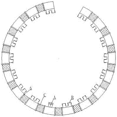
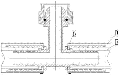
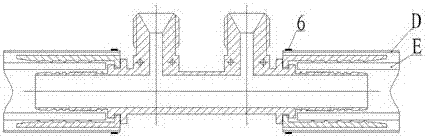
[0012] As shown in the figure, the present invention is composed of a flexible inner pipe (E), an oil inlet joint (A), sixteen double oil outlet joints (B) buckled and connected, and a heat-resistant sleeve (D) attached to the outer jacket . Among them, the flexible inner tube (E) is composed of a polytetrafluoroethylene inner tube (2) with a conductive coating (1) and an outer braided stainless steel wire braided reinforcement layer (3); the oil inlet joint (A) is an inner T-shaped Three-way stainless steel buckle joints are set in the middle of the pipeline; sixteen double oil outlet joints (B) are stainless steel buckle joints with inner π-shaped channels, and the flexible pipes are arranged equidistantly on both sides of the oil inlet. body (C); the heat-resistant sleeve (D) is composed of a glass fiber braided tube (4) ...


PUM


Abstract

The invention discloses a flexible fuel oil pipeline for power application of an aircraft engine and relates to fuel oil pipeline assembles for power application of aircraft engines. The flexible fuel oil pipeline is formed in the assembly mode that a flexible inner pipe, an oil inlet connector and sixteen double oil outlet connectors achieve buckling-pressing communicating, and a heat-resistant casing is arranged outside in a sleeving mode. The oil inlet connector is a three-way stainless steel buckling-pressing connector. The sixteen double oil outlet connectors are stainless steel buckling-pressing connectors internally provided with pi-shaped channels. The heat-resistant casing is formed in the mode that a silicone rubber layer is hung and attached outside a fiberglass woven barrel. An oil inlet and an oil outlet are both in the same plane on the same side of the axis of the pipeline, bending is achieved around the engine, and the oil inlet and the oil outlet are both formed fixedly and centripetally. Through the flexible fuel oil pipeline, the influence of thermal stress generated by an all-metal structure pipeline on an oil inlet header pipe can be eliminated, static electricity is conducted and removed in time, static seal is achieved, and danger brought by possible gas leakage is prevented. The heat-resistant casing can resist the high temperature of 1090+ / -80 DEG C and flame grilling of duration of 15 minutes, the operation stability of the whole pipeline is improved, and the safety of the whole machine is improved.

Description

technical field [0001] The invention relates to a fuel pipeline assembly for aircraft engine booster. Background technique [0002] At present, the fuel pipeline for engine afterburner of a certain type of domestic fighter uses an all-metal rigid pipeline. The pipeline is provided with an oil inlet communicated with the oil inlet main pipe and thirty-two oil outlets communicated with different controlled function valves of the engine, which are arranged on a plane metal pipe centripetally around the engine. The oil inlet manifold connected with the pipeline oil inlet is also metal, and it needs to pass through the afterburner outer casing and be fixed on the outer wall of the casing. Since the ambient temperature and working temperature of the pipeline vary greatly (between -50 and +250°C), the resulting thermal displacement is relatively large, so a large thermal stress is formed, thus affecting the safety and reliability of the rigid oil inlet manifold. and service life ...

Claims


Application Information

Patent Timeline
IPC IPC(8): F16L11/08F16L41/02F16L57/04
CPCF16L11/081F16L41/021F16L57/04
Inventor 张亮于雅洁皱永振付瑶贾荣真戴琳杨露虹
Owner SHENYANG RUBBER RES & DESIGN INST CO LTD
Why Eureka
Try Eureka