In-vitro visible interventional hemostasis device and method

A visual, body-surface technology, applied in the field of medical electronics, can solve problems such as the inability to intuitively judge the positional relationship of blood vessels, the accuracy of surgery needs to be improved, and the inconvenient operation, so as to improve the hemostatic effect, increase the success rate of hemostasis, and simplify the operation Effect

Pending Publication Date: 2022-04-01
中国人民解放军火箭军特色医学中心
0 Cites 0 Cited by

AI-Extracted Technical Summary

Problems solved by technology

However, because the hemostatic balloon is operated in the body, the doctor cannot intuitively judge the positional relationship between the bleedin...

Method used

The signal processing unit 6 realizes the synthetic registration of the spatial position of the hemostatic balloon 1 and the display unit 7 according to the spatial position of the hemostatic balloon 1 relative to the video image acquisition unit 5 by means of magnetic field positioning, and on the display unit 7 By fusing the images showing the patient's body surface, video data and the position information of the hemostatic balloon 1 in the patient's body, the position of the hemostatic balloon 1 in the patient's body can be observed at this time, which is convenient for doctors to perform hemostasis operations.
[0056] The video image acquisition unit 5 acquires the patient's body surface image or video data, and the captured patient's body surface image or video da...

Abstract

The invention provides an in-vitro visible interventional hemostasis device and a method thereof. The in-vitro visible interventional hemostasis device is characterized by mainly comprising a hemostasis balloon, a positioning sensor, a signal measurement unit, a video image acquisition unit, a signal processing unit and a display unit, the positioning sensor is located in the hemostasis balloon, and the positioning sensor is connected with the host through a wire; the signal processing unit is used for realizing synthetic registration of the spatial position of the hemostatic balloon and the display unit according to the spatial position of the hemostatic balloon relative to the video image acquisition unit; the display unit is used for fusing and displaying the body surface image or video information of the patient acquired by the video image acquisition unit and the position information of the hemostatic balloon in the body of the patient; the device can be used for stopping bleeding at a bleeding opening in vitro in an intuitive manner, can be used for accurately stopping bleeding at the bleeding position, greatly improves the bleeding stopping success rate and effect, and is high in operation precision and simple and convenient to operate.

Application Domain

Technology Topic

Image

  • In-vitro visible interventional hemostasis device and method
  • In-vitro visible interventional hemostasis device and method
  • In-vitro visible interventional hemostasis device and method

Examples

  • Experimental program(1)

Example Embodiment

[0048] In order to make the objectives, technical solutions and advantages of the present invention clearer, the present invention will be further described in detail below in conjunction with the specific embodiments and with reference to the accompanying drawings.
[0049] First, an in vitro visible interventional hemostatic device of the present invention is introduced:
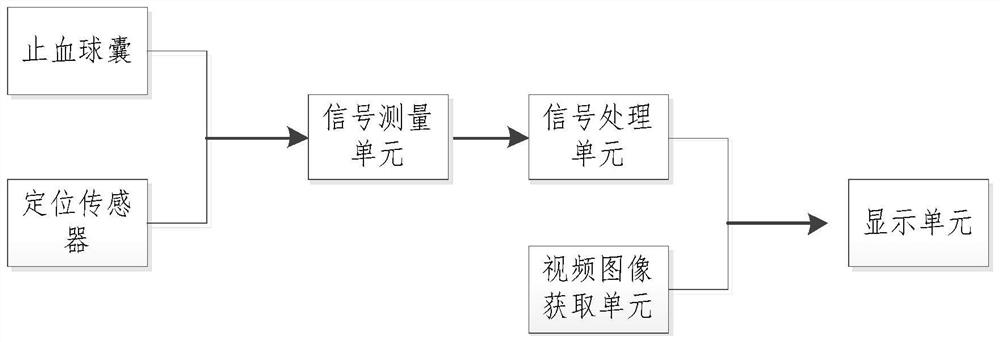
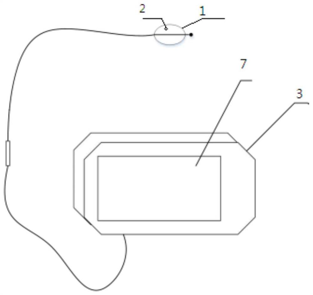
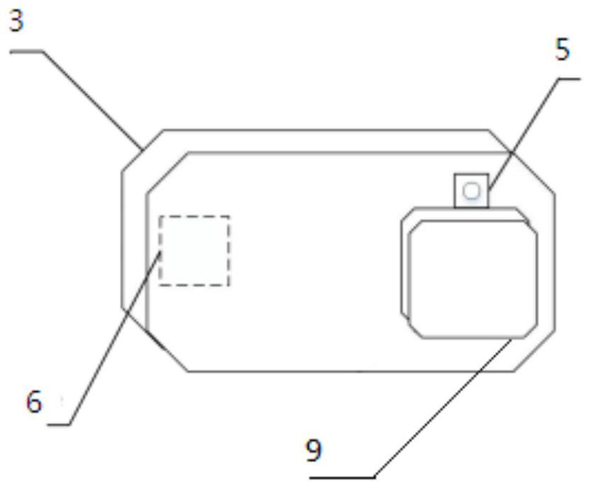
[0050] like Figure 1-Figure 3 and Image 6 As shown, an in vitro visible interventional hemostasis device of the present invention includes: a hemostatic balloon 1, a positioning sensor 2, a host 3, a signal measurement unit 4, a video image acquisition unit 5, a signal processing unit 6, a display unit 7, a magnetic field generator Coil 9.
[0051]The hemostatic balloon 1 is composed of a balloon catheter (with a balloon), an inflation joint, a rapid infusion assembly and a check valve. The hemostatic balloon 1 is used for hemostasis at the bleeding place of the patient, and the bleeding port is blocked by the pressure generated when the hemostatic balloon is inflated, so that the effect of rapid hemostasis can be achieved. When hemostasis is required, the hemostatic balloon 1 is disposed of into the blood vessel at the bleeding site through the interventional position 10 of the patient's body. When the hemostatic balloon 1 is reached, the hemostatic balloon 1 is inflated by injecting physiological saline into the hemostatic balloon 1 to generate inflation pressure. Block the bleeding port to achieve the effect of hemostasis. The hemostatic balloon 1 carries a positioning sensor, which can help to locate the position of the hemostatic balloon 1 .
[0052] The positioning sensor 2 is located inside the hemostatic balloon 1 and is connected to the host through a wire, and uses the magnetic field positioning method to perform real-time positioning on the positioning of the hemostatic balloon 1 . A magnetic field generating coil is set in the host, and a positioning sensor generates a positioning signal representing the position of the hemostatic balloon by inducing the magnetic field.
[0053] The host 3 includes a signal measurement unit 4 , a video image acquisition unit 5 , a signal processing unit 6 , and a display unit 7 .
[0054] The signal measuring unit 4 is used for receiving the positioning signal transmitted by the positioning sensor 2 , and obtaining the spatial position of the hemostatic balloon 1 according to the positioning signal.
[0055] The signal processing unit 6 is used to receive the collected positioning signal for the hemostatic balloon 1, and perform the magnetic field spatial positioning algorithm calculation on the collected positioning information. The signal processing unit 6 is used to obtain the unit according to the relative video image of the hemostatic balloon 1. 5 to realize the synthetic registration of the spatial position of the hemostatic balloon 1 and the display unit 7 . The position information calculation method for magnetic field spatial positioning will be described in detail below. The body surface image or video information of the patient captured by the video image acquisition unit and the position information of the hemostatic balloon in the patient's body are transmitted to the signal processing unit in a wired manner.
[0056] The video image acquisition unit 5 acquires the body surface image or video data of the patient, and the captured body surface image or video data of the patient can be displayed in real time through the display unit 7, which is convenient for the doctor to treat the patient's condition intuitively.
[0057] The display unit 7 is configured to fuse and display the body surface image or video data of the patient acquired by the video image acquisition unit 5 and the position information of the hemostatic balloon 1 in the patient's body. It is convenient for the doctor to accurately grasp the real-time position of the hemostatic balloon 1 when treating the patient, so that the bleeding can be accurately stopped. The position information of the hemostatic balloon 1 displayed on the display unit 7 is a cursor or other definite indicator. The image information displayed by the display unit 7 may be two-dimensional or three-dimensional.
[0058] The host 3 can be designed to be hand-held, so that the doctor can photograph the human body from different angles through the device of the present invention, so that the position of the hemostatic balloon 1 in the human body can be confirmed from different perspectives.
[0059] The device used in the in vitro visualization method applied to the hemostatic balloon of the present invention is the above-mentioned in vitro visible interventional hemostasis device.
[0060] An in vitro visualization method applied to a hemostatic balloon of the present invention includes the following steps:
[0061] (1) Obtain the image or video information of the patient's body surface through the video image obtaining unit 5 and transmit the obtained information to the display unit 7;
[0062] (2) displaying the image or video information of the patient's body surface through the display unit 7;
[0063] (3) During the process of placing the hemostatic balloon 1 in the patient, the display unit 7 fuses and displays the image or video information of the patient's body surface and the position information of the hemostatic balloon 1 in the patient's body .
[0064] When the doctor stops the bleeding of the patient: (1) the video image acquisition unit 5 transmits the acquired image or video information of the patient's body surface to the display unit 7; (2) after the doctor determines the bleeding position information, the hemostatic balloon 1 The signal measuring unit 4 receives the positioning signal for the hemostatic balloon 1 transmitted by the positioning sensor 2, and obtains the spatial position of the hemostatic balloon 1 according to the positioning signal; (3) Signal The measurement unit 4 transmits the received spatial position information of the hemostatic balloon 1 to the signal processing unit 6; (4) the signal processing unit 6 locates the hemostatic balloon 1 according to the spatial position of the hemostatic balloon 1 relative to the video image acquisition unit 5 by means of magnetic field positioning , to realize the synthetic registration of the spatial position of the hemostatic balloon 1 and the display unit 7; (5) the display unit 7 fuses and displays the image of the patient's body surface, video data and the position information of the hemostatic balloon 1 in the patient's body; ( 6) According to the displayed position of the hemostatic balloon 1, the doctor accurately places the hemostatic balloon 1 on the wound that needs hemostasis, and injects physiological saline into the hemostatic balloon 1 to inflate the hemostatic balloon 1. The pressure squeezes the blood vessel wall, so that the bleeding blood vessel can be blocked, and the further outflow of blood from the patient's wound can be prevented; (7) When the doctor judges that it is not necessary to continue the hemostasis operation, the hemostatic balloon 1 can be withdrawn from the patient's body , the blood vessels return to normal blood supply.
[0065] It can be seen that the present invention adopts the principle of intracavity hemostasis of electromagnetic navigation, receives the signal sent by the balloon preset electromagnetic device through the in vitro electromagnetic signal receiver, accurately locates the position of the balloon, and the medical personnel determine the balloon according to the traveling of the electromagnetic signal in the blood vessel path. After reaching the target location, the balloon is released to block the aorta to complete hemostasis. Electromagnetic navigation technology avoids the blindness of balloon placement, is conducive to achieving precise hemostasis, and improves the effect and success rate of hemostasis.
[0066] like Figure 4-Figure 5 As shown, the signal processing unit 6 of the present invention adopts the following calculation method when determining the relative position of the hemostatic balloon 1:
[0067] (1) The position of the video image acquisition unit 5 is set as point 0, and the endpoint of the object whose position is to be determined is set as 5 points P 1 point, the coordinates of the video image acquisition unit 5, the object endpoint P 1 The coordinates of the points are expressed in the form of world coordinates, the world coordinate value c=(x, y, z) of point O represents the spatial position of the video image acquisition unit 5, and the world coordinates of the object endpoints represent the signal measurement unit 4. The spatial position of the hemostatic balloon 1 obtained by measuring and calculating the positioning signal provided by the positioning sensor 2; , so that P 1 to be displayed on the screen;
[0068] (2) Calculate the endpoint P of the object whose position is to be determined 1 The coordinates of the projection point on the projection screen 8 of the imaging component, the projection screen 8 is parallel to the xy coordinate axis, and the projection coordinates are normalized, that is, it is assumed that the length and width of the screen are 1;
[0069] (3) The world coordinate value c=(x, y, z) of the video image acquisition unit 5, this world coordinate is the spatial position of the video image acquisition unit 5, the opening angle α (camera parameter) of the camera component in the X direction, the camera The opening angle β of the component in the Y direction (camera parameter);
[0070] (4) For P 1 =(u 1 ,v 1 ) point, such as Figure 4-Figure 5 shown, P 1 The calculation of point coordinates mainly uses the principle of similar triangles, that is, the projection screen 8 of the camera component is moved along the Z axis, and when the screen 8 is moved to pass through P 1 position, P 1 Normalized coordinates P of the point on screen 8 1 (u 1 ,v 1 ) remain unchanged, use P 1 The coordinate position of the point coordinate position is subtracted from the coordinate position of the video image acquisition unit (5) to obtain their difference values ​​in each coordinate direction can get
[0071] The display unit 7 according to the coordinates (u 1 ,v 1 ) displays the position information of the hemostatic balloon 1 in the patient's body.
[0072] The signal processing unit 6 realizes the synthetic registration of the spatial position of the hemostatic balloon 1 and the display unit 7 according to the spatial position of the hemostatic balloon 1 relative to the video image acquisition unit 5 by means of magnetic field positioning. The image and video data of the patient's body surface and the position information of the hemostatic balloon 1 in the patient's body can be used to observe the position of the hemostatic balloon 1 in the patient's body, which is convenient for the doctor to perform hemostasis operations.
[0073] The above descriptions are only specific embodiments of the present invention, but the protection scope of the present invention is not limited thereto, and various modifications and changes can be made to the present invention. Any modification, equivalent replacement, improvement, etc. made within the spirit and principle of the present invention shall be included within the protection scope of the present invention.

PUM

no PUM

Description & Claims & Application Information

We can also present the details of the Description, Claims and Application information to help users get a comprehensive understanding of the technical details of the patent, such as background art, summary of invention, brief description of drawings, description of embodiments, and other original content. On the other hand, users can also determine the specific scope of protection of the technology through the list of claims; as well as understand the changes in the life cycle of the technology with the presentation of the patent timeline. Login to view more.

Similar technology patents

Bed-fixed type hemostasis support for cardiology department

InactiveCN114869387AAvoid wound dehiscenceImprove hemostatic effectDiagnosticsOperating tablesMedical staffEngineering
Owner:河南省胸科医院

Haemostasis and antibiosis band, and production method and application thereof

InactiveCN104888266AImprove hemostatic effectStrong anti-infection effectAdhesive dressingsAbsorbent padsDrugDisinfectant
Owner:李平

Novel microporous medical hemostatic material and preparation method thereof

ActiveCN103349791AImprove hemostatic effectEasy to swellAbsorbent padsBlood disorderCorn starchPanax notoginseng extract
Owner:GUANGXI XINYE BIOLOGICAL TECH

Anorectal postoperative hemostasis device

PendingCN114246630AImprove hemostatic effectImprove securitySurgeryMedical applicatorsElectric heatingBandage
Owner:山东大学齐鲁医院(青岛)

Nasal cavity hemostasis device for blood disease patient

InactiveCN113425356AImprove hemostatic effectBalloon catheterSurgeryEngineeringHematologic disease
Owner:SHAANXI UNIV OF CHINESE MEDICINE

Classification and recommendation of technical efficacy words

  • Improve hemostatic effect

Novel microporous medical hemostatic material and preparation method thereof

ActiveCN103349791AImprove hemostatic effectEasy to swellAbsorbent padsBlood disorderCorn starchPanax notoginseng extract
Owner:GUANGXI XINYE BIOLOGICAL TECH

Haemostasis and antibiosis band, and production method and application thereof

InactiveCN104888266AImprove hemostatic effectStrong anti-infection effectAdhesive dressingsAbsorbent padsDrugDisinfectant
Owner:李平

Nasal cavity hemostasis device for blood disease patient

InactiveCN113425356AImprove hemostatic effectBalloon catheterSurgeryEngineeringHematologic disease
Owner:SHAANXI UNIV OF CHINESE MEDICINE

Bed-fixed type hemostasis support for cardiology department

InactiveCN114869387AAvoid wound dehiscenceImprove hemostatic effectDiagnosticsOperating tablesMedical staffEngineering
Owner:河南省胸科医院

Anorectal postoperative hemostasis device

PendingCN114246630AImprove hemostatic effectImprove securitySurgeryMedical applicatorsElectric heatingBandage
Owner:山东大学齐鲁医院(青岛)
Why Eureka
Try Eureka