
Heat dissipation and cooling device for engine

A cooling device and engine technology, which is applied in the direction of engine components, machine/engine, engine cooling, etc., can solve the problems of large cooling fan power consumption, energy consumption, environmental pollution, etc., and achieve the effect of simple circuit and high intelligence

Pending Publication Date: 2022-04-01
JILIN TEACHERS INST OF ENG & TECH
View PDF4 Cites 0 Cited by
  • Summary
  • Abstract
  • Description
  • Claims
  • Application Information

AI Technical Summary

Problems solved by technology

[0002] With the continuous growth of the automobile industry, it provides convenience for people, but also brings a series of problems such as energy consumption and environmental pollution. Among them, the automobile engine is easy to cause engine damage due to excessive temperature and unfavorable heat dissipation during work. Damage, in the prior art, temperature control has a wide range of applications, but in the temperature control of automobile engines, only cooling water or cooling fans are used to dissipate heat from the automobile engine, and the cooling water is prone to overcooling or exhaustion of cooling water Due to this phenomenon, the temperature cannot be lowered. The cooling fan has achieved the cooling effect by removing the hot air through the principle of commutation, and the power consumption of the cooling fan is too large, so it needs to be improved.

Method used


Image

  • Heat dissipation and cooling device for engine
  • Heat dissipation and cooling device for engine
  • Heat dissipation and cooling device for engine

Examples


Embodiment 1

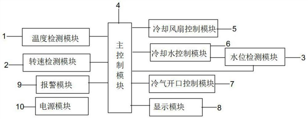
[0018] Embodiment 1: see figure 1 The embodiment of the present invention provides a heat dissipation and cooling device for an engine. The heat dissipation and cooling device for an engine includes: a temperature detection module 1, a rotational speed detection module 2, a water level detection module 3, a main control module 4, and a cooling fan control module 5. Cooling water control module 6, air-conditioning opening control module 7;

[0019] Specifically, the temperature detection module 1 is connected with the main control module 4 for detecting the temperature of the automobile engine and outputting temperature information;

[0020] A rotational speed detection module 2, connected to the main control module 4, for detecting the rotational speed of the cooling fan and outputting rotational speed information;

[0021] The water level detection module 3 is connected with the main control module 4, and is used to detect the cooling water level and output the water level i...

Embodiment 2

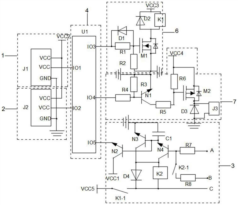
[0032] Embodiment 2: On the basis of Embodiment 1, please refer to figure 2 , in a specific embodiment of the engine heat dissipation and cooling device described in the present invention, the temperature detection module 1 includes a temperature sensor J1; the speed detection module 2 includes a speed sensor J2; the power module 10 includes a second power supply VCC2 ; The main control module 4 includes a first controller U1;

[0033] Specifically, the power supply terminal of the temperature sensor J1 and the power supply terminal of the rotational speed sensor J2 are both connected to the second power supply VCC2, the ground terminal of the temperature sensor J1 and the ground terminal of the rotational speed sensor J2 are both grounded, and the output terminal of the temperature sensor J1 and The output terminals of the rotational speed sensor J2 are respectively connected to the first IO terminal and the second IO terminal of the first controller U1.

[0034] Further, t...

Embodiment 3

[0042] Embodiment 3: On the basis of Embodiment 2, please refer to image 3 , in a specific embodiment of a heat dissipation and cooling device for an engine according to the present invention, the specific steps of the workflow of each module are as follows:

[0043] S1, start;

[0044] S2, device initialization;

[0045] S3, module initialization;

[0046] S4, the temperature detection module 1 detects whether the temperature exceeds the first temperature threshold, if so, enters S5, otherwise enters S8;

[0047] S5, 6 subroutines of the cooling water control module, used to control the work of the cooling water module;

[0048] S6, water level detection module 3 subroutines, used to detect the water level situation in the cooling water tank;

[0049] S7. Whether the cooling water level is lower than the minimum water level, if yes, enter S10, otherwise, enter S5;

[0050] S8. Detect whether the temperature exceeds the second temperature threshold, if yes, enter S9, oth...


PUM


Abstract

The invention discloses a heat dissipation and cooling device for an engine, which relates to the technical field of engine control and comprises a temperature detection module, a rotating speed detection module, a water level detection module, a main control module, a cooling fan control module, a cooling water control module and a cold air opening control module. The temperature detection module detects the temperature of an engine, the rotating speed detection module detects the rotating speed of a cooling fan, the water level detection module detects the water level of cooling water, the main control module receives information and works, the cooling fan control module controls the cooling fan, the cooling water control module controls cooling water, and the cold air opening control module controls a cold air opening. According to the cooling device for the engine, the cooling fan control module, the cooling water control module and the cold air opening control module are matched with the temperature detection module to work, different modules are adopted for cooling the automobile engine at different temperatures, and the cooling device is further provided with the water level detection module.

Description

technical field [0001] The invention relates to the technical field of engine control, in particular to a heat dissipation and cooling device for an engine. Background technique [0002] With the continuous growth of the automobile industry, it provides convenience for people, but also brings a series of problems such as energy consumption and environmental pollution. Among them, the automobile engine is easy to cause engine damage due to excessive temperature and unfavorable heat dissipation during work. Damage, in the prior art, temperature control has a wide range of applications, but in the temperature control of automobile engines, only cooling water or cooling fans are used to dissipate heat from the automobile engine, and the cooling water is prone to overcooling or exhaustion of cooling water Due to this phenomenon, the temperature cannot be lowered. The cooling fan has achieved the cooling effect by removing the hot air through the principle of commutation, which ma...

Claims


Application Information

Patent Timeline
Patent Type & Authority Applications(China)
IPC IPC(8): F01P9/04F01P9/06F01P7/04F01P7/14F01P7/02F01P11/14F01P11/18
Inventor 齐万强霍金明于继东孙英杰黄合成
Owner JILIN TEACHERS INST OF ENG & TECH
Learn More