Cleaning head, cleaning device and cleaning method

A technology of cleaning equipment and cleaning head, which is applied in the direction of cleaning equipment, vacuum cleaners, household utensils, etc., to achieve the effect of quick cleaning

Pending Publication Date: 2022-04-05
TIANKE INTELLIGENT TECH CO LTD
View PDF0 Cites 1 Cited by
  • Summary
  • Abstract
  • Description
  • Claims
  • Application Information

AI Technical Summary

Problems solved by technology

However, stubborn dirt such as serious oil stains are still difficult to clean

Method used


Image

  • Cleaning head, cleaning device and cleaning method
  • Cleaning head, cleaning device and cleaning method
  • Cleaning head, cleaning device and cleaning method

Examples


application example 1

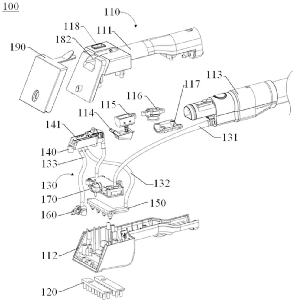
[0086] In Application Example 1, a cleaning head 100 is provided, which can be installed in various types of cleaning equipment such as vacuum cleaners, mite removing machines, carpet and curtain cleaning machines, cleaning robots, etc., where the types of cleaning equipment in this application example Not specifically limited. The cleaning head 100 includes a body 110, a cleaning piece 120, a distribution pipeline 130, a distribution device 140, a first spray device 150 and a second spray device 160, wherein the distribution pipeline 130, the distribution device 140 and At least one of the second spraying devices 160 has a speed-increasing structure, and the speed-up structure enables the cleaning medium to flow in the second spraying device 160 compared with that in the first spraying device. 150 has a larger outlet flow rate, and the second spray device 160 can be used for fixed-point cleaning of stubborn stains.

application example 2

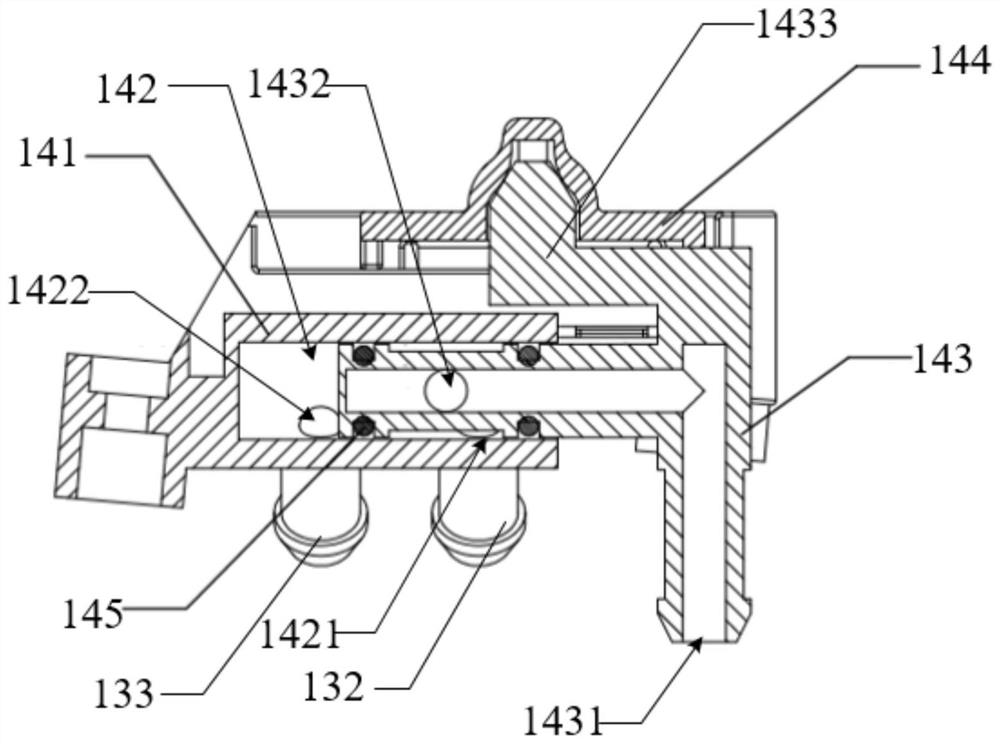
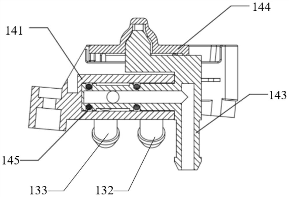
[0088] In the second application example, the structure of the cleaning head 100 is substantially the same as that in the first application example, the difference being that the distribution device 140 in this application example specifically includes a distribution seat 141 and a switching member 143 . Wherein, the distribution base 141 has a distribution cavity 142, and the distribution cavity 142 has a first interface 1421 and a second interface 1422, the first interface 1421 communicates with the first spray device 150, and the second The interface 1422 is connected to the second spraying device 160; the switching member 143 has an inlet port 1431 and an outlet port 1432, and the inlet port 1431 is used for receiving cleaning medium. Here, when the switching member 143 is located at the first position, the cleaning medium may be supplied to the first shower device 150 . When the switching member 143 is in the second position, the cleaning medium can be supplied to the sec...

application example 3

[0090] In the third application example, the structure of the cleaning head 100 is substantially the same as that in the first application example, the difference is that the first spray device 150 specifically includes a plate-shaped spray seat 152, the spray A medium flow channel is arranged inside the seat 152 and several first spray ports 151 communicated with the medium flow channel are arranged on its surface, and the first spray ports 151 are evenly spaced so as to achieve a uniform spray effect. The second shower device 160 only includes a second shower port 161 . The first shower device 150 has a larger coverage area than the second shower device 160 .


PUM


Abstract

The invention provides a cleaning head, cleaning equipment and a cleaning method, a distribution device is arranged in a distribution pipeline of the cleaning equipment, and the distribution device enables the distribution pipeline to provide a cleaning medium for a first spraying device and/or a second spraying device in a controllable mode. And at least one of the distribution pipeline, the distribution device and the second spraying device is provided with a speed increasing structure, and the speed increasing structure enables the cleaning medium to have a higher outlet flow speed in the second spraying device than in the first spraying device. During use, different cleaning modes are selected according to different requirements of cleaning scenes, cleaning objects and the like, the second spraying device can be adopted for achieving fixed-point stain cleaning for small-range stains, and the second spraying device can be adopted for achieving large-area rapid cleaning for large-range stains. And the cleaning medium can be heated through the heating device, so that the working mode of the heating device can be switched among a normal temperature mode, a heating mode and a steam mode.

Description

technical field [0001] The present application relates to the technical field of cleaning equipment, in particular to a cleaning head, cleaning equipment and a cleaning method. Background technique [0002] The descriptions in this section merely provide background information related to the disclosure in this application and may not constitute prior art. [0003] Cleaning equipment such as vacuum cleaners can be used to clean floors, walls, furniture, carpets, clothes, and the like. Generally, the cleaning equipment is provided with a cleaning part and a water spray port facing the surface to be cleaned, wherein the cleaning part can be a disc brush, a flat brush, a rolling brush, etc., which are used to contact the surface to be cleaned and perform cleaning work. The water spray port can spray water or other cleaning media to the surface to be cleaned, so that the cleaning part can achieve a better cleaning effect. However, stubborn dirt such as relatively serious oil st...

Claims


Application Information

Patent Timeline
Patent Type & Authority Applications(China)
IPC IPC(8): A47L7/00A47L9/00A47L9/02
Inventor 钱文琪王云飞李彦卿易生尧
Owner TIANKE INTELLIGENT TECH CO LTD
Why Eureka
Try Eureka