Smart community Internet of Things video monitoring device
A technology for video surveillance and the Internet of Things, applied in TV, color TV, CCTV systems, etc., can solve problems such as fire damage to electronic equipment, circuit short-circuit, electronic equipment short-circuit fire, etc., to avoid short-circuit fire and improve safety.
- Summary
- Abstract
- Description
- Claims
- Application Information
AI Technical Summary
Problems solved by technology
Method used
Image
Examples
Embodiment 1
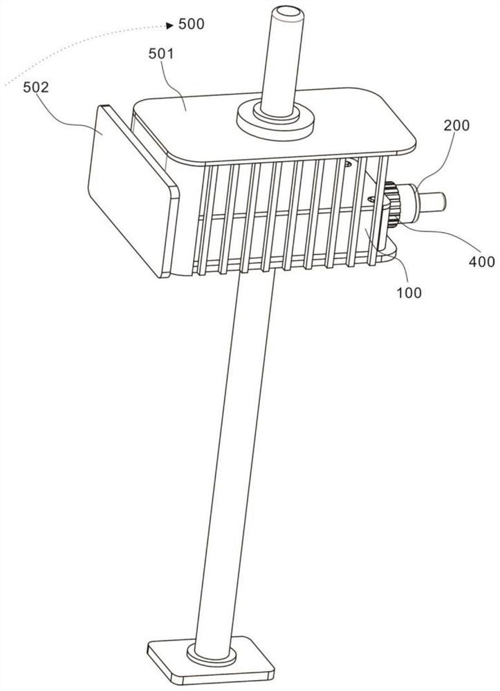
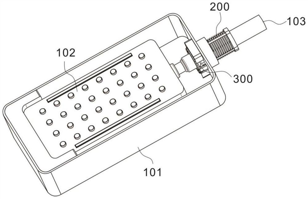
[0029] Example 1: Please refer to figure 1 and figure 2 ,, the present invention provides a smart community Internet of Things video monitoring device, including, equipment components 100, including a housing 101, the inner cavity of the housing 101 is provided with an electronic component 102, the wiring port of the electronic component 102 is connected to a power cord 103, and the power cord 103 Through the shell 101; the sealing assembly 200 includes a positioning ring 201 embedded in the surface of the shell 101, a movable ring 202 is provided on one side of the positioning ring 201, and the movable ring 202 is sleeved on the power cord 103 to prevent the entry of sundries and water vapor; Withdrawal assembly 300, the exit assembly 300 is set in the inner cavity of the housing 101, so that the power line 103 is separated from the electronic components, avoiding the problem of short circuit and fire, and making emergency response in time, protecting the electronic equipmen...
Embodiment 2
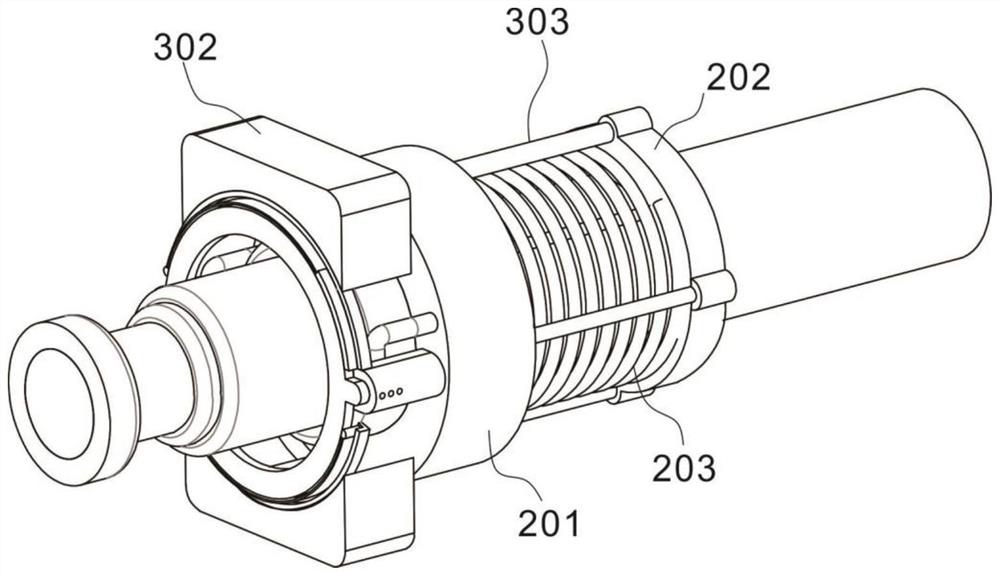
[0030] Example 2: Please refer to Figure 3-5 One side of the movable ring 202 is fixedly connected with a limit spring 203, and the end of the limit spring 203 is in movable contact with the surface of the positioning ring 201. The movable penetrating positioning ring 201 extends into the inner cavity of the housing 101 , the positioning ring 201 is provided with a rod hole adapted thereto, and the surface of the movable ring 202 is provided with integrally formed bumps.
[0031] The positioning ring 201 is provided with a U-shaped tube 205 on the surface close to the inner cavity of the housing 101, and the ends of the struts 204 are movably inserted into the U-shaped tube 205, and the ends of the U-shaped tube 205 are inserted into the inner cavity of the positioning ring 201, and the U-shaped The end of the tube 205 is connected to one end of the curved conduit 206, and the other end of the curved conduit 206 is connected to the sealing gas ring 209. During the installatio...
Embodiment 3
[0035] Example 3: Please refer to image 3 , Figure 5 and Image 6The exit assembly 300 includes a guide sleeve 301 which is arranged in the inner cavity of the casing 101 and is fixedly connected with the positioning ring 201. A vertically symmetrical concave block 302 is arranged on one side of the guide sleeve 301. The inner surface of the concave block 302 has an arcuate structure, and The inner surface of the concave block 302 is provided with an arc guide rail 305, and a connecting shaft 309 is movable on the arc guide rail 305. The movement of the movable ring 202 drives the withdrawal rod 303 to send the withdrawal ring 304 to the arc guide rail 305 side, and The connecting shaft 309 is connected with the withdrawal ring 304 and rotated a little, so that the protrusion on the surface of the withdrawal ring 304 snaps into the limit groove on the limit platform 306. The return spring 310 embedded on the arc guide rail 305 .
[0036] The connecting shaft 309 is a rota...
PUM
 Abstract
Description
Claims
Application Information
 - R&D
- Intellectual Property
- Life Sciences
- Materials
- Tech Scout
- Unparalleled Data Quality
- Higher Quality Content
- 60% Fewer Hallucinations
Browse by: Latest US Patents, China's latest patents, Technical Efficacy Thesaurus, Application Domain, Technology Topic, Popular Technical Reports.
© 2025 PatSnap. All rights reserved.Legal|Privacy policy|Modern Slavery Act Transparency Statement|Sitemap|About US| Contact US: help@patsnap.com


