Winding and unwinding mechanism

A technology for winding and unwinding rolls and reels, which is applied in the field of coil material unwinding and unwinding equipment, can solve problems such as poor alignment accuracy of reels, low loading and unloading efficiency, and affecting the quality of coil materials, so as to ensure quality, improve stability and uniformity , the effect of enhancing security

Pending Publication Date: 2022-04-08
HUIZHOU YINGHE TECH
View PDF0 Cites 2 Cited by
  • Summary
  • Abstract
  • Description
  • Claims
  • Application Information

AI Technical Summary

Problems solved by technology

[0004] In order to solve the problems that the existing winding and unwinding equipment has poor alignment accuracy of the reels, low loading and unloading efficiency, which affects the quality of the coil material, and easy to drop the roll when unloading, the invention provides a winding and unwinding mechanism

Method used


Image

  • Winding and unwinding mechanism
  • Winding and unwinding mechanism
  • Winding and unwinding mechanism

Examples


Embodiment 1

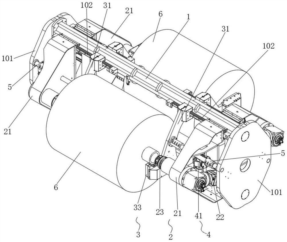
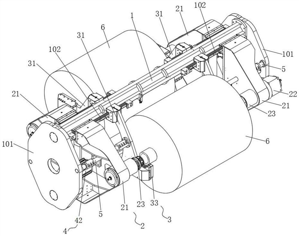
[0037] For the winding and unwinding mechanism of the present invention, please refer to figure 1 and figure 2 As shown, it is a schematic diagram of the axial structure of the winding and unwinding mechanism from the first direction and the second direction respectively, and the first direction and the second direction can be specifically the right front side direction and the left front side direction as shown in the figure.

[0038] The winding and unwinding mechanism is provided with a support 1, and the support 1 has a beam running along the left and right directions, and side plates 101 are fixedly connected to the left and right ends of the beam. In addition, a winding assembly 2 and a reel positioning support assembly 3 are arranged on the support 1 . Wherein, the winding assembly 2 and the reel positioning support assembly 3 are connected to the beam of the bracket 1, and the positions of the winding assembly 2 and the reel positioning support assembly 3 on the brac...

Embodiment 2

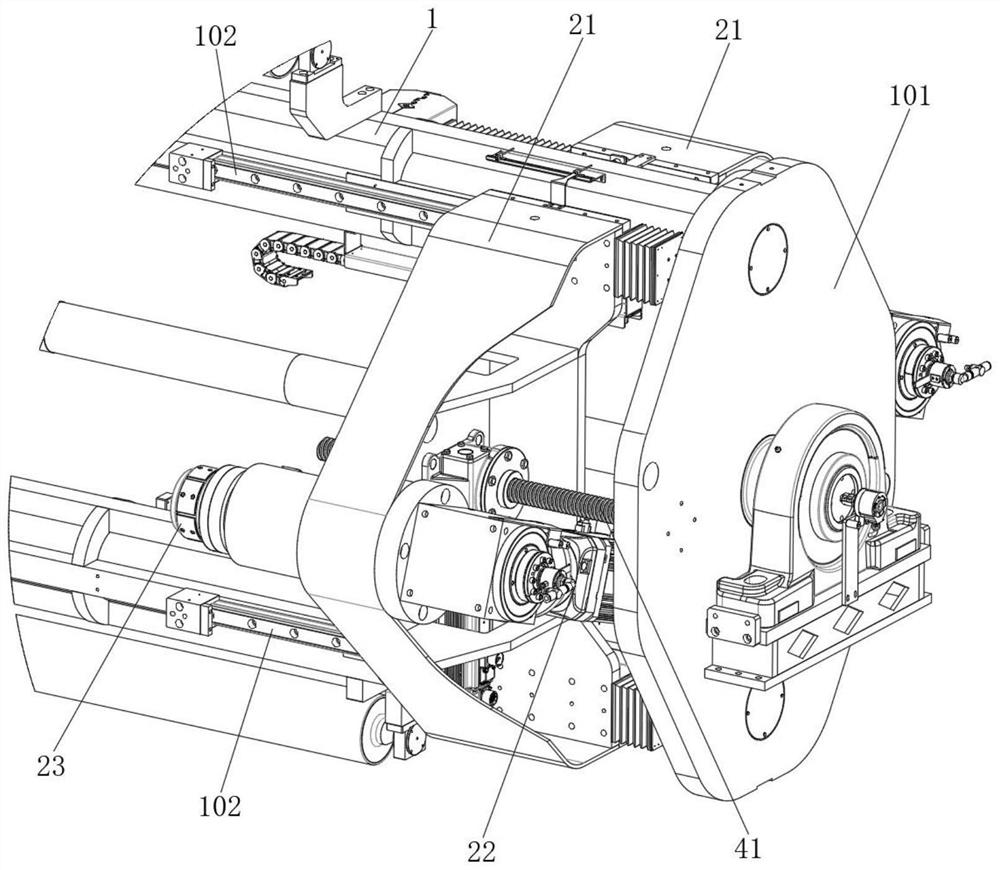
[0046] This embodiment is the same as Embodiment 1. Further, see image 3 As shown, in the retracting and unwinding mechanism of this embodiment, the winding assembly 2 further includes a first support arm 21, wherein the rotating drive member 22 and the reel clamp 23 are both arranged on the first support arm 21; and, the first support arm 21 The support arm 21 is connected to the beam of the bracket 1 and can move left and right relative to the beam of the bracket 1 for adjustment.

[0047] In the specific embodiment shown, a slide rail 102 along the left-right direction is arranged on the crossbeam of the bracket 1, and the first support arm 21 is slidably arranged on the slide rail 102 through a slider, and can move along the slide rail 102 Adjust the position left and right.

[0048] Optionally, the first support arm 21 has a V-shaped arm structure, the support 1 at least includes vertically arranged beams, the slide rails 102 are arranged on the vertically arranged bea...

Embodiment 3

[0053] This embodiment is the same as Embodiment 1 or Embodiment 2. further, please see figure 1 and figure 2 As shown, in the winding and unwinding mechanism of this embodiment, the reel positioning support assembly 3 further includes a second support arm 31 . Moreover, the second support arm 31 is connected to the crossbeam of the bracket 1 , and can move left and right relative to the crossbeam of the bracket 1 .

[0054] In the specific embodiment shown, a slide rail 102 along the left-right direction is provided on the crossbeam of the bracket 1, and the second support arm 31 is slidably arranged on the slide rail 102 through a slider, and can move along the slide rail. 102 moves to adjust the left and right positions.

[0055] Optionally, the second support arm 31 has a V-shaped arm structure, and the support 1 at least includes vertically arranged beams, on which the slide rails 102 are arranged, and the support bracket 33 and the lifting drive member 32 are both pr...


PUM


Abstract

The invention discloses a winding and unwinding mechanism. The winding and unwinding mechanism comprises a support, a winding assembly and a reel positioning and supporting assembly. The winding assembly and the reel positioning and supporting assembly are both arranged on the support, and the positions of the winding assembly and the reel positioning and supporting assembly on the support are adjustable in the axial direction of winding and unwinding of a material reel. When material rolls are fed and discharged, the reel positioning and supporting assembly serves as an auxiliary mechanism for feeding and discharging operation, manual feeding and discharging or automatic feeding and discharging can be met, the fed and discharged material rolls are accurately positioned and supported, the feeding and discharging speed of the material rolls is increased, and the production efficiency is improved. And a reel clamp in the winding assembly can conveniently and accurately clamp or loosen a reel to accurately position, so that the production efficiency is improved, the winding and unwinding stability and uniformity of the coil stock are improved, and the quality of the coil stock is ensured. In addition, the winding and unwinding mechanism is wide in winding and unwinding applicability to material rolls with different widths and sizes.

Description

technical field [0001] The invention relates to the technical field of coil material retracting and unwinding equipment, in particular to a coil retracting and unwinding mechanism. Background technique [0002] In the production of lithium battery pole pieces or plastic films, since the produced pole pieces or films are transported and stored in the form of rolls, the corresponding rolls will be rewound and unwound. In the process of rewinding and unwinding of the material roll, the reel that has been positioned can be rewound or unrolled during the rotation process. [0003] Wherein, in the existing winding and unwinding process of the lithium battery pole piece, the coil material that has been wound up or the coil material to be unwound is manually unloaded or loaded. During the loading and unloading process of the lithium battery pole piece, it basically relies on manual support of the material roll. Due to the heavy weight of the lithium battery pole piece, not only the...

Claims


Application Information

Patent Timeline
Patent Type & Authority Applications(China)
IPC IPC(8): B65H75/38B65H19/12B65H19/30B65H75/44
Inventor 邢波唐存福邓荣峰姚蕾
Owner HUIZHOU YINGHE TECH
Why Eureka
Try Eureka