Synchronous belt transmission mechanism and telescope angle adjusting mechanism

A synchronous belt transmission and synchronous belt technology, applied in telescopes, transmissions, friction transmissions, etc., can solve the problems of increased noise, reduced tracking accuracy, increased friction, etc., to reduce operating noise, improve tracking accuracy, Realize the effect of power transmission

Pending Publication Date: 2022-04-08
NANTONG SCHMIDT OPTO ELECTRICAL TECH CO LTD
0 Cites 0 Cited by

AI-Extracted Technical Summary

Problems solved by technology

[0003] First, if the diameter of the synchronous wheel is very large, the diameter of the required synchronous belt must also be very large. At this time, it is extremely difficult to obtain a suitable synchronous belt, and even if a suitable synchronous belt can be found, its price is also very expensive
Second, in the field of astronomy, due to the large area of ​​the synchronous belt w...

Method used

Compared with the prior art, the synchronous belt drive mechanism of the present invention wraps the side of the endless synchronous belt without the toothed layer on the tensioning wheel group, and the endless synchronous belt is provided with the side of the toothed layer Peripherals, and mesh with the first synchronous wheel and the second synchr...

Abstract

The invention discloses a synchronous belt transmission mechanism and a telescope angle adjusting mechanism, the synchronous belt transmission mechanism comprises a first synchronous wheel, a second synchronous wheel, an annular synchronous belt and a tensioning wheel set, the outer surface of the first synchronous wheel and the outer surface of the second synchronous wheel are each provided with a plurality of teeth, the annular synchronous belt is arranged on the tensioning wheel set in a sleeving mode, a belt tooth layer is formed on the outer surface of the annular synchronous belt, and the belt tooth layer is in meshing tooth connection with the first synchronous wheel and the second synchronous wheel. According to the synchronous belt transmission mechanism, the side, provided with the belt tooth layer, of the annular synchronous belt is externally arranged, and the annular synchronous belt is meshed with the first synchronous wheel and the second synchronous wheel through a small contact surface, so that power transmission is achieved, operation noise is lowered, and the tracking precision of a telescope is improved.

Application Domain

Technology Topic

Image

  • Synchronous belt transmission mechanism and telescope angle adjusting mechanism
  • Synchronous belt transmission mechanism and telescope angle adjusting mechanism

Examples

  • Experimental program(1)

Example Embodiment

[0018] DETAILED DESCRIPTION OF THE PREFERRED EMBODIMENT OF THE INVENTION The specific embodiments of the present invention will be described in detail below, but it should be understood that the scope of the invention is not limited by the specific embodiments.
[0019] Unless otherwise clear, otherwise, in the entire specification and claims, the term "comprising" or "including" or "comprising" or the like will be understood to include the components or components of the present, and Other components or other components are not excluded.
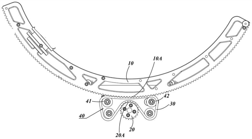
[0020] Such as figure 2 As shown, an embodiment of the present invention provides a synchronous belt transmission mechanism including a first housing 10, a second synchronous wheel 20, a ring synchronous tape 30, and a tensioning wheel group 40. The tensioning wheel group 40 is disposed between the first housing 10 and the second synchronous wheel 20, and the ring synchronous belt 30 is set on the tensioning wheel set 40, and rod to the first homage 10 and the second synchronization wheel 20, respectively. connect.
[0021] The ring synchronous belt 30 is formed along the side of its radial direction (not shown), and a teeth are provided with an equal spacing on the surface of the tooth layer. The circumferential surface of the first housing 10 and the second synchronous wheel 20 is provided with a tooth with a tooth layer, a tooth spacing of the first homing wheel 10 and the second synchronous wheel 20 weeks, equal to the band tooth of the ring synchronous belt 30. Layer tooth spacing. The annular synchronous belt 30 has a side outer valve with a tooth layer, engaged with the first housing 10 and the second synchronous wheel 20, and the annular synchronous belt 30 is not in contact with the tensioning wheel group 40.
[0022] The first housing 10 and the second synchronizing wheel 20 have a relatively close first surface segment 10a and the second surface segment 20a, and the tape layer of the annular synchronous strip 30 engages the first surface segment 10a and the second surface segment 20a, respectively.
[0023] In an embodiment, the tensioning wheel group 40 includes three fixed tension wheels 41 and a tonable tension wheel 42. The annular synchronous belt is set in four tension wheels (41/42), forming a quadrigid structure, and the first housing 10 and the second synchronous wheel 20 each engaged on different sides of the four-bodies structure. The adjustable tension wheel 42 can be moved relative to the fixed tension wheel 41 to adjust the engaging pine duration between the annular synchronous belt 30 and the first housing 10 and the second synchronous wheel 20.
[0024] In a specific embodiment, the number of adjustable tension wheels 42 can also be two or more.
[0025] In a specific embodiment, the diameter of the first housing 10 is greater than the diameter of the second synchronous wheel 20. The first housing 10 and the second synchronous wheel 20 respectively engage the two edges of the four-bodies structure.
[0026] In a specific embodiment, the first housing 10 having a large diameter may not be a complete circular gear, and may be part of a complete circular gear.
[0027] In an embodiment, the present invention also provides a telescope angular adjustment mechanism including the above-described synchronous belt transmission mechanism.
[0028] Compared with the prior art, the synchronous belt transmission mechanism of the present invention is wrapped on the ring synchronous belt on the tensioning wheel, and the annular synchronization belt is provided with a tooth layer. And with the first synchronization wheel and the second synchronization wheel with a small contact surface, the ring synchronization belt is adjusted between the ring synchronous belt and the first and second synchronization wheels by one or more adjustable tensioners. Tight, thus realizing power transmission, reducing operation noise, and improving the tracking accuracy of telescope.
[0029] The foregoing description of the specific exemplary embodiments of the present invention is for purposes of illustration and illustration. These descriptions are not intended to define the present invention as the disclosed precise form, and it is clear that many changes and variations can be made according to the above teachings. An object of selecting and description of an exemplary embodiment is to explain a particular principle of the present invention and its practical applications thereof, thereby enabling various exemplary embodiments of the invention and various different exemplary embodiments of the present invention. Select and change. The scope of the invention is intended to be limited by the claims and equivalents thereof.

PUM

no PUM

Description & Claims & Application Information

We can also present the details of the Description, Claims and Application information to help users get a comprehensive understanding of the technical details of the patent, such as background art, summary of invention, brief description of drawings, description of embodiments, and other original content. On the other hand, users can also determine the specific scope of protection of the technology through the list of claims; as well as understand the changes in the life cycle of the technology with the presentation of the patent timeline. Login to view more.

Similar technology patents

Half-bridge resonant wireless energy transmission system

ActiveCN107681791ARealize power transmissionHigh Efficiency Power TransmissionCircuit arrangementsElectric energyResonator
Owner:厦门金固美能源科技有限公司

Classification and recommendation of technical efficacy words

Why Eureka
Try Eureka