Mobile equipment with wireless charging and discharging function and device

A mobile device and functional technology, applied in the field of electricity, can solve problems such as high cost, high price, and short life

Inactive Publication Date: 2016-01-20
NINGBO LIKETEK INFORMATION TECH
View PDF9 Cites 3 Cited by
  • Summary
  • Abstract
  • Description
  • Claims
  • Application Information

AI Technical Summary

Problems solved by technology

[0003] The cost of existing wireless charging products is very high, especially the price of the charging board is expensive, which is often more than 100 yuan, which has a negative effect on the further promotion and development of wireless charging technology. If a lower-cost wireless charging product can be developed, it will benefit wireless Further promotion and development of charging technology
[0004] After searching the patent database, the inventor found that the invention patent with the application number 201410065211.3 named "a wireless charging and discharging circuit, terminal equipment and wireless discharging method" is the technology closest to the present invention. Due to the design restrictions of the 201410065211.3 patent ( or limit of thinking), the inventor has adopted two relays with two branches to switch the connection between the receiving circuit and the transmitting circuit to the coil, so as to realize the sharing of a coil between the transmitting circuit and the receiving circuit; the relay is used as an electronic switch in many Among the electronic components, they are expensive and fragile components, with short life and high price, and there is room for improvement

Method used


Image

  • Mobile equipment with wireless charging and discharging function and device
  • Mobile equipment with wireless charging and discharging function and device
  • Mobile equipment with wireless charging and discharging function and device

Examples


Embodiment 1

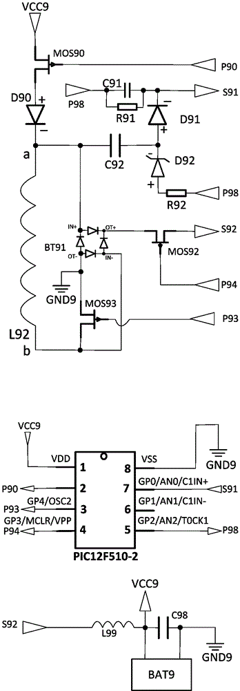
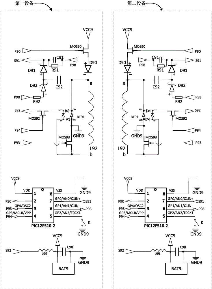
[0093] Implementation example 1, such as figure 1 As shown, a mobile device with wireless charging and discharging function is characterized in that it includes a transmitting switch MOS90, a protection diode D90, a high-pass filter capacitor C92, a sampling ground P98, a voltage regulator tube D92, a half-wave rectifier diode D91, and a sampling resistor R91 , current limiting resistor R92, sampling capacitor C91, rectifier bridge BT1, power receiving switch MOS92, power receiving control point P94, switch MOS93, coil L2, power point VCC9, location GND9, emission control point P90, power receiving point S92, switching Control point P93, sampling output point S91, microcontroller PIC12F510-2, rechargeable battery BAT, low-pass filter inductor L99, power output capacitor C98;

[0094] The emission switch MOS90 has a controlled channel and a control terminal. When the level of the control point of the emission switch MOS90 is high, the controlled channel of the emission developm...

Embodiment 2

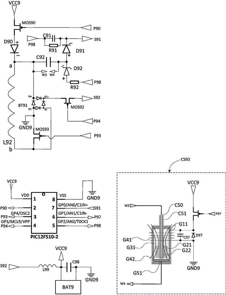
[0116] Implementation example 2, such as figure 2 , a mobile device with a wireless charging and discharging function, characterized in that it includes a transmitting switch MOS90, a protection diode D90, a high-pass filter capacitor C92, a sampling ground P98, a voltage regulator tube D92, a half-wave rectifier diode D91, a sampling resistor R91, a limiter Current resistor R92, sampling capacitor C91, rectifier bridge BT1, power receiving switch MOS92, power receiving control point P94, switch MOS93, coil L2, power point VCC9, location GND9, emission control point P90, power receiving point S92, switching control point P93, sampling output point S91, microcontroller PIC12F510-2, rechargeable battery BAT, low-pass filter inductor L99, power output capacitor C98, controllable capacitor CS92;

[0117] The emission switch MOS90 has a controlled channel and a control terminal. When the level of the control point of the emission switch MOS90 is high, the controlled channel of the...

Embodiment 3

[0151] Implementation example 3, a mobile device with wireless charge and discharge function as described in implementation example 2, characterized in that there is a gap between the bottom electrode G51 of the controllable capacitor CS92 and the second point W4 of the controlled channel of the controllable capacitor CS92 There is a ball switch in series to prevent capacitors from being used if they are not placed correctly.


PUM


Abstract

The invention relates to mobile equipment with a wireless charging and discharging function, which is characterized by further comprising a transmitting switch (MOS90), a protection diode (D90), a high-pass filtering capacitor (C92), a sampling site (P98), a voltage stabilizing tube (D92), a half-wave rectification diode (D91), a sampling resistor (R91), a current-limiting resistor (R92), a sampling capacitor (C91), a rectifier bridge (BT1), an electric energy receiving switch (MOS92), an electric energy receiving control point (P94), a change-over switch (MOS93), a coil (L2), a power supply point (VCC9), a ground point (GND9), a transmission control point (P90), an electric energy receiving point (S92), a switching control point (P93), a sampling output point (S91), a single chip microcomputer (PIC12F510-2), a rechargeable battery (BAT), a low-pass filtering inductor (L99) and a power supply output capacitor (C98). The invention further relates to a device, which is additionally provided with a control program on the basis of the solution. The mobile equipment and the device provided by the invention are low in cost, flexile in application, long in service life and capable of mutually transmitting electric energy and information.

Description

technical field [0001] The invention belongs to the field of electricity, and relates to a mobile device and a device with wireless charging and discharging functions. Background technique [0002] Wireless charging technology is a technology that utilizes magnetic resonance, electromagnetic resonance or electromagnetic induction to realize power transmission without wires; the cost of wireless charging products in the prior art is high and there is room for reduction; the wireless charging products in the prior art can realize There are very few products that transmit power between devices with batteries (that is, devices that can be powered by their own rechargeable batteries), and products that can transmit power between devices with batteries and transmit information through their coils Fewer, there is a need for further development. [0003] The cost of existing wireless charging products is very high, especially the price of the charging board is expensive, which is o...

Claims


Application Information

Patent Timeline
Patent Type & Authority Applications(China)
IPC IPC(8): H02J50/10H02J7/00H04B1/40
Inventor 林谷
Owner NINGBO LIKETEK INFORMATION TECH
Why Eureka
Try Eureka