Motor bearing fault diagnosis method and device based on signal enhancement and compression edge calculation

A technology for fault diagnosis device and motor bearing, which is applied to services, measurement devices, signal transmission systems based on specific environments, etc., and can solve problems such as busy transmission channels, sudden increase in computing and storage pressure in data centers, etc.

Inactive Publication Date: 2020-10-30
ANHUI UNIVERSITY
View PDF3 Cites 0 Cited by
  • Summary
  • Abstract
  • Description
  • Claims
  • Application Information

AI Technical Summary

Problems solved by technology

[0005] In recent years, the number of deployments of IoT devices has grown rapidly, and the resulting problem is that th

Method used


Image

  • Motor bearing fault diagnosis method and device based on signal enhancement and compression edge calculation
  • Motor bearing fault diagnosis method and device based on signal enhancement and compression edge calculation
  • Motor bearing fault diagnosis method and device based on signal enhancement and compression edge calculation

Examples


Example Embodiment

[0073] Example 1:

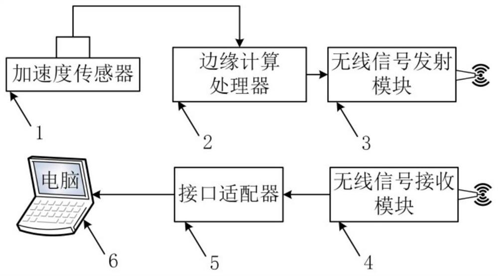
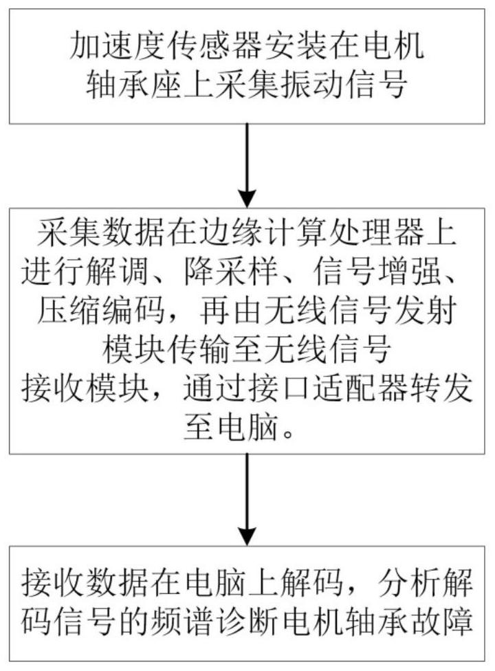
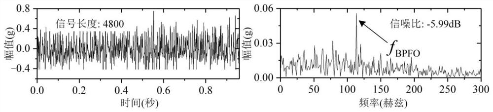
[0074] This embodiment illustrates the practicability and superiority of the present invention by analyzing the fault signal of the outer ring of the motor bearing. The model of the motor bearing is 6002Z, and the motor speed is 1283RPM. From this, the characteristic frequency f of the outer ring fault of the bearing can be calculated BPFO It is 115.6 Hz. use figure 1 As shown in the IoT node device proposed by the present invention, according to step 1 of the method of the present invention, the acceleration sensor in the device of the present invention is installed on the motor bearing seat. Set the sampling frequency to 5kHz, the sampling time to 0.96 seconds, and the collected data points to 4800.

[0075] According to step 2 of the method of the present invention, the signal is demodulated, down-sampled and signal enhanced on the edge computing processor. The square low-pass filtering algorithm of the present invention is used to demodulate the signal, ...

Example Embodiment

[0077] Example 2:

[0078] In order to further demonstrate the superiority of the method of the present invention, the transmission time, power consumption and other performances of the method of the present invention and the traditional method are compared through experiments. The method of the present invention includes 4 stages of signal acquisition, signal preprocessing, signal compression and signal transmission. The signal preprocessing includes demodulation, down-sampling and signal enhancement processes. The traditional method only includes two stages of signal acquisition and signal sending, that is, the collected data is sent directly to the computer for processing without processing. The comparison results of the two methods are as follows Figure 7 As shown, Figure 7 The above is the power consumption diagram of the method of the present invention. It can be seen from the diagram that the power consumption curve changes dynamically with the execution of the algorithm...


PUM


Abstract

The invention discloses a motor bearing fault diagnosis method and device based on signal enhancement and compression edge calculation. The method comprises the steps: (1) installing an acceleration sensor on a motor bearing pedestal to collect vibration signals; (2) performing demodulation, downsampling and signal enhancement on the acquired signals in an edge computing processor, performing compressed encoding on the processed data, transmitting the data to a wireless signal receiving module through a wireless signal transmitting module, and transmitting the data to a computer through an interface adapter; and (3) decoding the received data in a computer, and carrying out spectral analysis on the decoded signal to diagnose the bearing fault type. The method has the advantages that the data is compressed and enhanced by adopting edge calculation on the Internet of Things node, the signal-to-noise ratio of the output signal can be improved, the length of the signal needing to be sent is reduced, the sending time and power consumption are reduced, the bearing fault diagnosis efficiency is finally improved, and the service life of a battery of the Internet of Things node is prolonged.

Description

technical field [0001] The invention relates to the technical field of online diagnosis of motor bearing faults, in particular to a motor bearing fault diagnosis method and device based on signal enhancement and compression edge calculation. Background technique [0002] Motors are widely used in industrial production. Industrial motors are prone to performance degradation and mechanical and electrical failures after long-term operation. Studies have shown that 40%-50% of motor failures are caused by bearings, so it is of great significance to monitor the condition and diagnose faults of motor bearings. Vibration signal analysis is a common technology for motor fault diagnosis. The acceleration sensor installed on the motor bearing seat collects the motor vibration signal, and the signal processing and analysis can determine the fault type and fault severity of the motor bearing. [0003] Noise interference is the key core problem faced by motor bearing fault diagnosis. Th...

Claims


Application Information

Patent Timeline
IPC IPC(8): G01M13/045H04W4/38G08C17/02
CPCG01M13/045H04W4/38G08C17/02Y02D30/70
Inventor 陆思良汤华松王骁贤刘永斌王群京
Owner ANHUI UNIVERSITY
Why Eureka
Try Eureka