An optical imaging structure

An optical imaging and optical glass technology, applied in optics, optical components, instruments, etc., can solve the problems of weak three-dimensional perception, inability to achieve aerial imaging, and inability to present images, and achieve accurate imaging results.

Active Publication Date: 2022-06-28
北京谛听视界文化科技有限公司
View PDF0 Cites 0 Cited by
  • Summary
  • Abstract
  • Description
  • Claims
  • Application Information

AI Technical Summary

Problems solved by technology

[0003] Today's optical imaging equipment can only present the visual effect of an infinitely extended tunnel, and cannot display images in the middle of the tunnel, and cannot achieve the effect of aerial imaging. At the same time, the content displayed by existing optical imaging technology is presented through the visual difference between the background space and the foreground image. Three-dimensional sense, relatively weak three-dimensional sense

Method used


Image

  • An optical imaging structure
  • An optical imaging structure
  • An optical imaging structure

Examples


Embodiment Construction

[0027] The technical solutions in the embodiments of the present invention will be clearly and completely described below with reference to the accompanying drawings in the embodiments of the present invention. Obviously, the described embodiments are only a part of the embodiments of the present invention, but not all of the embodiments. Based on the embodiments of the present invention, all other embodiments obtained by those of ordinary skill in the art without creative efforts shall fall within the protection scope of the present invention.

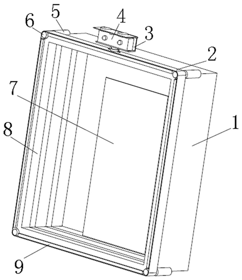
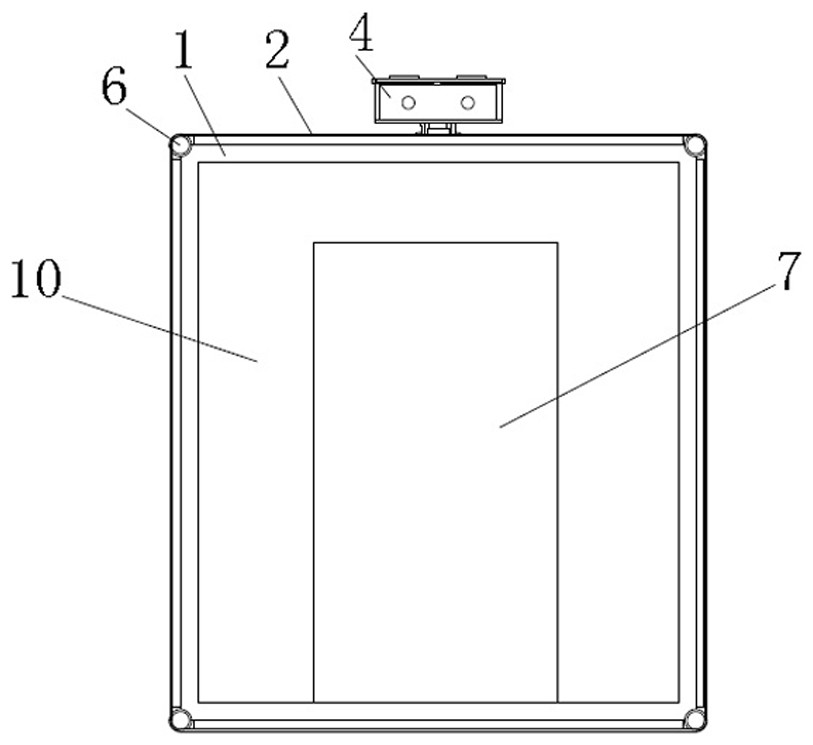
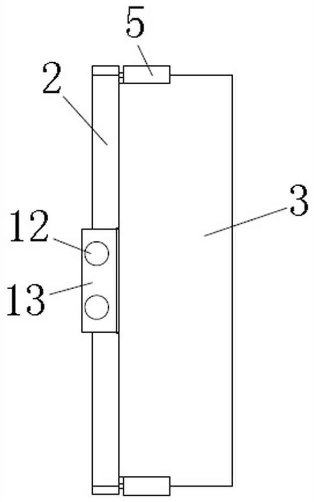
[0028] see figure 1 , figure 2 , image 3 , Figure 5 , Image 6 , Figure 7 , Figure 8 , The present invention provides an optical imaging structure (equipment) for realizing naked eye 3D optical imaging. Included optical imaging assembly and user tracking assembly. The optical imaging assembly is used to generate an image. The user tracking component is used to track the eyes and / or head of the user, determine the orientat...


PUM


Abstract

The present invention relates to the technical field of display devices, in particular to an optical imaging structure, including: an optical imaging component, including a frame, a display screen, a light-emitting element, optical glass and a mirror surface, the optical glass is fixedly installed on one side of the frame, and the mirror surface is fixedly installed on the frame On the other side, several light-emitting elements are fixedly installed on the inner wall of the frame; the present invention presents an infinitely extended tunnel vision through repeated reflection between the mirror surface and the optical glass, and the image displayed on the display screen is in the middle of the infinitely extended tunnel Floating display, the image and the subsequent tunnel space form a visual distance difference, showing the visual effect of floating imaging. Through the detection of the viewer's position and data algorithm processing by the eye tracking device and holographic processing platform, the holographic image can be adjusted in time. The display angle enables the viewer to always observe the image angle of the correct perspective relationship, combined with the visual effect of floating imaging, so as to realize the visual effect of naked-eye 3D floating imaging.

Description

technical field [0001] The invention relates to the technical field of display devices, in particular to an optical imaging structure. Background technique [0002] Light is everywhere around us. Optical imaging is a technology that uses the characteristics of light for imaging. Optical imaging technology is used in all fields of our lives, including cameras, video cameras, telescopes, projectors, etc. Through the structure of optical imaging, it is also The effect of naked eye 3D can be formed. Naked eye 3D is a general term for technologies that achieve stereoscopic visual effects without external tools such as polarized glasses. The representatives of this type of technology mainly include light barrier technology and cylindrical lens technology. [0003] Today's optical imaging equipment can only present the visual effect of infinitely extending the tunnel, and cannot present images in the middle of the tunnel, and cannot achieve the effect of aerial imaging. At the same...

Claims


Application Information

Patent Timeline
Patent Type & Authority Patents(China)
IPC IPC(8): G02B30/56G02B27/00G06V40/19G06V10/764
Inventor 张喆
Owner 北京谛听视界文化科技有限公司
Why Eureka
Try Eureka