Zero-incisura conjoined screw for adjacent vertebral bodies

A zero-notch, screw technology, applied in the direction of internal fixator, internal bone synthesis, fixator, etc., can solve the problems of easy loosening, non-rotation resistance, and easy fracture of screws, and achieves increased anti-rotation balance, strong stability, Strong pull-out effect

Pending Publication Date: 2022-04-12
洪琦
View PDF18 Cites 0 Cited by
  • Summary
  • Abstract
  • Description
  • Claims
  • Application Information

AI Technical Summary

Problems solved by technology

[0002] At present, the existing cancellous vertebral body screws are easy to loose, easy to pull out, easy to break, not resistant to rotation and other failu

Method used


Image

  • Zero-incisura conjoined screw for adjacent vertebral bodies
  • Zero-incisura conjoined screw for adjacent vertebral bodies
  • Zero-incisura conjoined screw for adjacent vertebral bodies

Examples


Embodiment 1

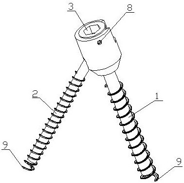
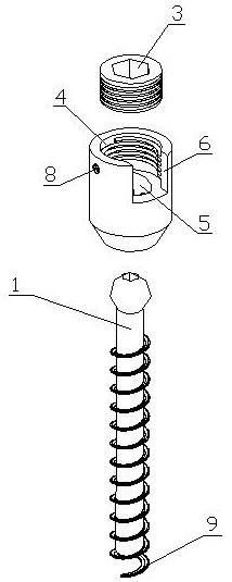
[0036] Embodiment 1: The doctor fixes the main screw 1 on the patient's vertebral body, inserts the auxiliary screw 2 into the screw oblique insertion hole 5 through the screw receiving groove 4, fixes the auxiliary screw 2 on another adjacent vertebral body, and The locking nut 3 is screwed into the screw receiving groove 4 to compress and fix the auxiliary screw 2 .

Embodiment 2

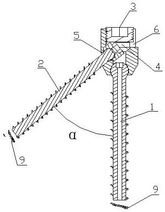
[0037] Embodiment 2: The doctor fixes the main screw 1 on the patient's vertebral body, inserts the auxiliary screw 2 into the screw oblique insertion hole 5 through the screw receiving groove 4, and fixes the auxiliary screw 2 on another adjacent vertebral body. The locking nut 3 is screwed into the screw receiving groove 4 to compress and fix the auxiliary screw 2 . Because the auxiliary screw 2 is relatively large, it is difficult to put it directly through the screw receiving groove 4, and it is more convenient to insert the screw mounting groove 6 into the screw oblique insertion hole 5.

Embodiment 3

[0038] Embodiment 3: The doctor fixes the main screw 1 on the patient's vertebral body, inserts the auxiliary screw 2 into the screw oblique insertion hole 5 through the screw receiving groove 4, fixes the auxiliary screw 2 on another adjacent vertebral body, and The locking nut 3 is screwed into the screw receiving groove 4 to compress and fix the auxiliary screw 2 . The lock nut 3 is pressed on the horizontal pressing surface 7 to make the lock nut 3 more stable.


PUM


Abstract

A zero-incisura conjoined screw for adjacent vertebral bodies comprises a main screw (1), an auxiliary screw (2) and a locking nut (3), a screw containing groove (4) is formed in the top of a screw cap of the main screw (1), a screw inclined inserting hole (5) is formed in the bottom of the screw containing groove (4), a screw rod of the auxiliary screw (2) is inserted into the screw inclined inserting hole (5), and the screw cap of the auxiliary screw (2) is located in the screw containing groove (4). Internal threads are arranged on the inner wall of the upper portion of the screw containing groove (4), the locking nut (3) is installed in the screw containing groove (4) in a threaded mode, and a nut cap of the auxiliary screw (2) is pressed in the screw containing groove (4) through the locking nut (3); the device has the advantages that the device is small in size, minimally invasive, high in pulling resistance and stability and high in rotation resistance balance; 2, the device can be used for partial surface replacement of cancellous centrum, thighbone lower end and tibia knee joint surface;

Description

technical field [0001] The invention relates to the field of medical equipment, in particular to a zero-profile conjoined screw for adjacent vertebral bodies. Background technique [0002] At present, the existing cancellous vertebral body screws are easy to loose, easy to pull out, easy to break, not resistant to rotation and other failure conditions. Lack of a kind of volume less, anti-loosening, not easy to pull out, not easy to break, anti-rotation cancellous vertebral screw. Contents of the invention [0003] The object of the present invention is to provide a zero-profile conjoined screw for adjacent vertebral bodies to address the above-mentioned deficiencies. [0004] The present invention includes main screw, secondary screw and lock nut, [0005] The top of the nut of the main screw is provided with a screw receiving groove, and the bottom of the screw receiving groove is provided with a screw oblique insertion hole. The screw rod of the auxiliary screw is inse...

Claims


Application Information

Patent Timeline
IPC IPC(8): A61B17/86A61B17/70
Inventor 洪琦洪紫荊李芳
Owner 洪琦
Why Eureka
Try Eureka