Optical lens shell maintenance device

An optical lens and housing technology, which is applied in the field of optical lens housing maintenance devices, to achieve the effect of preventing dust from entering the interior of the outer frame, avoiding influence, and reducing the difficulty of operation

Active Publication Date: 2022-04-12
上饶市兴杰达光电科技有限公司
View PDF11 Cites 1 Cited by
  • Summary
  • Abstract
  • Description
  • Claims
  • Application Information

AI Technical Summary

Problems solved by technology

[0005]Aiming at the deficiencies of the prior art, the present invention provides an optical lens housing maintenance device capable of fixing the lens housing, so as to overcome the need for manual adjustment of the existing device Disadvantages of fixing optical lenses

Method used


Image

  • Optical lens shell maintenance device
  • Optical lens shell maintenance device
  • Optical lens shell maintenance device

Examples


Embodiment 1

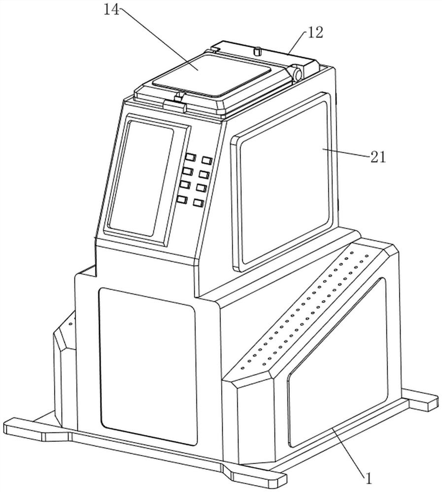
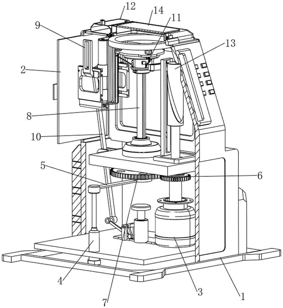
[0094] see figure 1 , figure 2 , image 3 and Figure 4 , a maintenance device for an optical lens housing, comprising an outer frame 1, a revolving door 2, a first transparent glass 21, a motor 3, a cylinder 4, a pressing plate 5, a first full gear 6, a second full gear 7, and a support frame 8 , a cleaning mechanism 9, a pushing mechanism 10 and a limit mechanism 11, the front side of the top of the outer frame 1 has a discharge port, the rear upper side of the outer frame 1 is hinged with a revolving door 2, and the left and right sides of the upper part of the outer frame 1 are symmetrically embedded. The first transparent glass 21, the first transparent glass 21 is convenient for people to observe the progress of the work, the front side of the inner bottom of the outer frame 1 is fixedly connected with a motor 3 by bolts, the output shaft of the motor 3 is connected with the first full gear 6 by a key, and the outer frame 1 The rear side of the middle part is connect...

Embodiment 2

[0100] On the basis of Example 1, please refer to figure 1 , Figure 13 , Figure 14 and Figure 15 , also includes a storage mechanism 12, the storage mechanism 12 is used to store the maintenance fluid, the storage mechanism 12 includes a storage box 121, a box cover 122, a hose 123, a pressing rod 124 and a third telescopic spring 125, and the rear side of the top of the outer frame 1 A storage box 121 is provided. The storage box 121 is used to store maintenance fluid. A detachable box cover 122 is installed in the middle of the top of the storage box 121. The box cover 122 is used to close the storage box 121. A hose 123 is provided in the middle of the front lower side of the storage box 121. , the hose 123 passes through the discharge port and is connected to the rear upper side of the discharge pipe 911, and the middle part of the front lower side of the storage box 121 is slidably connected with a pressing rod 124. The tube 123 is clamped, and two third telescopic ...


PUM


Abstract

The invention relates to a shell maintenance device, in particular to an optical lens shell maintenance device. The invention provides an optical lens shell maintenance device capable of fixing a lens shell. An optical lens shell maintenance device comprises an outer frame. The upper rear side of the outer frame is rotationally connected with the rotating door; the left side and the right side of the upper portion of the outer frame are symmetrically connected with the first transparent glass. The front side of the bottom in the outer frame is connected with the motor; an output shaft of the motor is connected with the first full gear; the rear side of the middle of the outer frame is rotationally connected with the rotating shaft, and the lower side of the rotating shaft is connected with the second full gear. The upper side of the interior of the sliding block is an inclined plane, and the roller rolls along with the inclined plane to drive the rotating rod to rotate towards the inner side, thereby driving the sliding block to move towards the outer side, enabling the sliding block to support the lens housing, and achieving the purpose of fixing the lens housing.

Description

technical field [0001] The invention relates to a housing maintenance device, in particular to an optical lens housing maintenance device. Background technique [0002] Optical lenses are generally used in cameras and video cameras and other shooting machines. Optical lenses can affect the quality of imaging. The optical lens housing needs to be maintained regularly to reduce the loss of the optical lens housing and extend the service life of the optical lens. [0003] The existing maintenance device includes an outer frame, a revolving door, the first transparent glass and a support frame. People first place the lens case on the top of the support frame, then clean the lens case with the help of cleaning equipment, and wipe the maintenance liquid. People manually wipe the optical lens housing, but this device needs to manually fix the lens housing, and the fixing effect is relatively poor. [0004] Therefore, it is necessary to develop an optical lens housing maintenance d...

Claims


Application Information

Patent Timeline
Patent Type & Authority Applications(China)
IPC IPC(8): B08B1/00B08B13/00B08B17/04B05C13/02B05C11/10B05C11/02B05C1/02
Inventor 曾婷
Owner 上饶市兴杰达光电科技有限公司
Why Eureka
Try Eureka