
Jumper wire adaptive positioning device capable of realizing rapid disassembly and assembly

A positioning device, jumper wire technology, applied in auxiliary devices, welding equipment, auxiliary welding equipment and other directions, can solve the problem of inability to perform accurate and fast welding due to infinite characteristics

Pending Publication Date: 2022-04-12
BEIJING INST OF RADIO MEASUREMENT
View PDF7 Cites 0 Cited by
  • Summary
  • Abstract
  • Description
  • Claims
  • Application Information

AI Technical Summary

Problems solved by technology

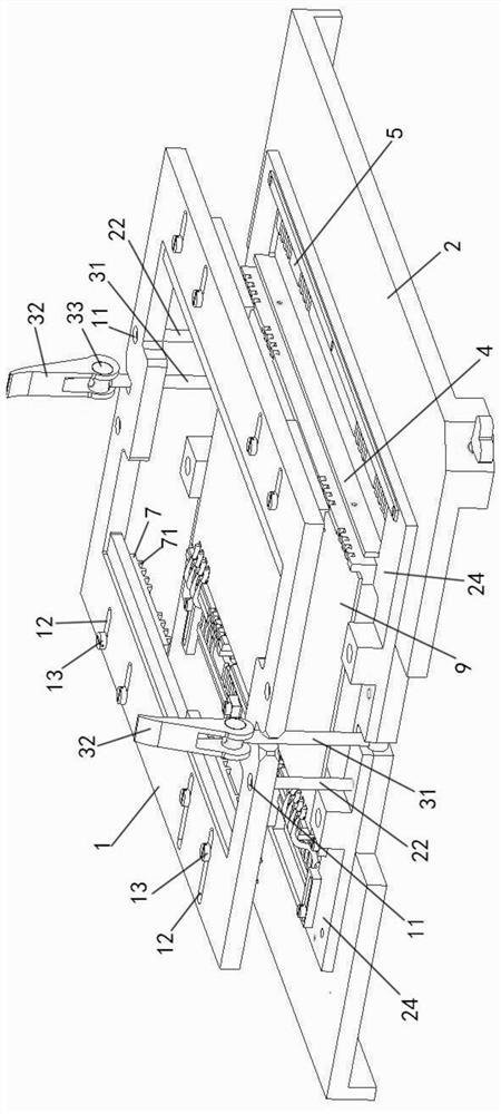
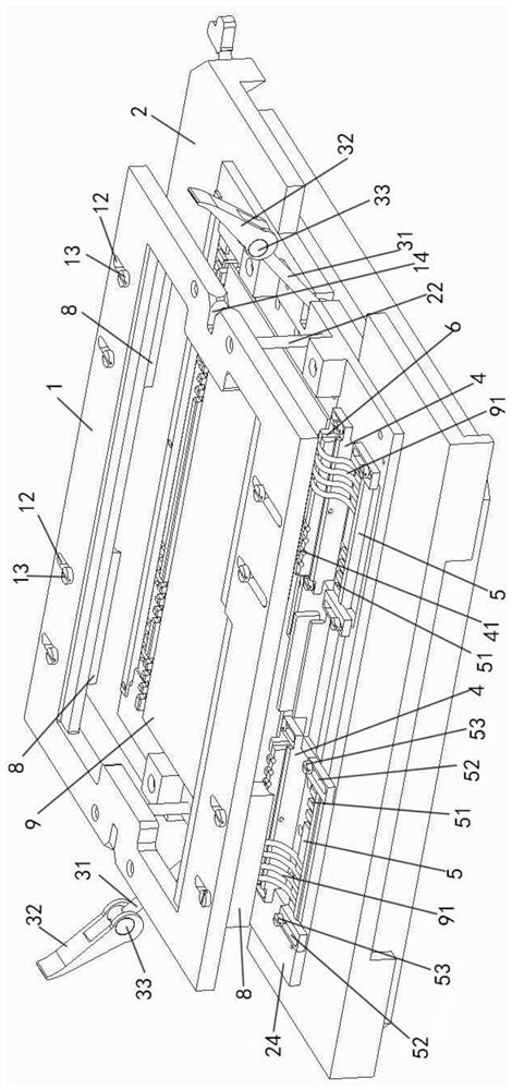
[0007] The beneficial effects of the present invention are: the present invention compresses and positions the jumper wires in the lower positioning groove through the corresponding arrangement of the upper positioning assembly and the lower positioning groove, and can realize quick disassembly and adaptive positioning of the jumper wires, thereby solving the problem of The problem that the jumper's own elasticity and the infinite position characteristics of the surface mount assembly cannot be accurately and quickly welded

Method used


Image

  • Jumper wire adaptive positioning device capable of realizing rapid disassembly and assembly
  • Jumper wire adaptive positioning device capable of realizing rapid disassembly and assembly
  • Jumper wire adaptive positioning device capable of realizing rapid disassembly and assembly

Examples


Embodiment Construction

[0050] The principles and features of the present invention will be described below with reference to the accompanying drawings, and the exemplary examples are intended to be construed as not intended to limit the scope of the invention.

[0051] Such as Figure 8 As shown, the printed plate is mounted in the printed plate assembly frame 24 as the center of the jumper 91 as the center of the bridge, and the front end of the placement position of the bridge 91, the printed plate assembly hollow 21 side as a bridge wire 91 The rear end of the placed, both the cross wire 91 are arranged around the printed plate, so that the cross-wiring 91 is placed across the wire 91 in the printed plate assembled, so that the front end 92 of the cross-wiring 91 is close to the printing. The panel assembles the direction of the hollow 21 extends, so that the wire rear end 93 of the cross wire 91 is arranged in a direction away from the printed plate to assemble the hollow 21.

[0052] Such as Figure ...


PUM


Abstract

The invention relates to a jumper wire adaptive positioning device capable of realizing rapid disassembly and assembly, which comprises an upper cover, a printed board assembly frame, an upper positioning assembly, a lower positioning assembly and a locking mechanism, and is characterized in that the locking mechanism is mounted on the upper cover or the printed board assembly frame and is used for locking the upper cover and the printed board assembly frame when the upper cover is pressed on the printed board assembly frame; the upper positioning assembly is installed on the lower side face of the upper cover, the lower positioning assembly is installed on the upper side face of the printed board assembling frame, a lower positioning groove is formed in the lower positioning assembly, and the upper positioning assembly corresponds to the lower positioning groove of the lower positioning assembly and is used for pressing and positioning the jumper wire in the lower positioning groove. The jumper wire in the lower positioning groove is pressed and positioned through corresponding arrangement of the upper positioning assembly and the lower positioning groove, and the upper cover and the printed board assembly frame are locked through the locking mechanism, so that positioning and locking of the jumper wire are realized, quick disassembly and assembly and adaptive positioning of the jumper wire can be realized, and the service life of the jumper wire is prolonged. The problem that accurate and rapid welding cannot be carried out due to the elasticity of the jumper wire and the limitation-free characteristic of surface-mounted assembly is solved.

Description

Technical field [0001] The present invention relates to the field of electronic flux, and more particularly to a cross-line adaptive positioning device that enables rapid disassembly. Background technique [0002] In the era of modern rapid assembly, the welding of the printing element of the printed board has been applied very widely, but the mountable wires are also available on the printed panel products, in order to improve welding efficiency, the same It is necessary to achieve rapid welding. [0003] However, different from the insertion component can be limited by the weld hole of the printed board, and the mounting wire itself is a surface of the printed board. Therefore, the wire will appear when soldering. Offset; [0004] Therefore, it is necessary to implement the rapid welding of the mountable wire, requires special process devices, constraints on the formation of the wires and the position of the welding, because such welding conditions are generally existed on the ...

Claims


Application Information

Patent Timeline
Patent Type & Authority Applications(China)
IPC IPC(8): B23K37/04
Inventor 王季张明亮麻思达陈朝峰马壮李斌
Owner BEIJING INST OF RADIO MEASUREMENT
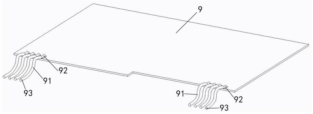
Learn More