
Low-cost electric nail gun

A low-cost, electric technology, applied in the field of nail guns, can solve the problems of high manufacturing cost and high cost of one-way bearings, achieve low cost, improve support stability, and prevent reverse rotation.

Pending Publication Date: 2022-04-12
HANGZHOU KELONG ELECTRICAL APPLIANCE TOOLS
View PDF0 Cites 0 Cited by
  • Summary
  • Abstract
  • Description
  • Claims
  • Application Information

AI Technical Summary

Problems solved by technology

Since the outer peripheral surface of the convex pin in the prior art is a circumferential surface, when the convex pin is at a high position, the convex pin forms a line contact with the hammer, and the convex pin will reversely rotate under the reaction force of the elastic element. In order to ensure that the convex pin Can stagnate at a high position, a one-way bearing needs to be installed between the casing of the motor and the motor shaft to prevent the cam pin from rotating in reverse. Because the cost of the one-way bearing is high, the manufacturing cost of the product is also high

Method used


Image

  • Low-cost electric nail gun
  • Low-cost electric nail gun
  • Low-cost electric nail gun

Examples


Embodiment Construction

[0037] The technical solutions of the embodiments of the present invention will be explained and described below in conjunction with the accompanying drawings of the embodiments of the present invention, but the following embodiments are only preferred embodiments of the present invention, not all of them. Based on the examples in the implementation manners, other examples obtained by those skilled in the art without making creative efforts all belong to the protection scope of the present invention.

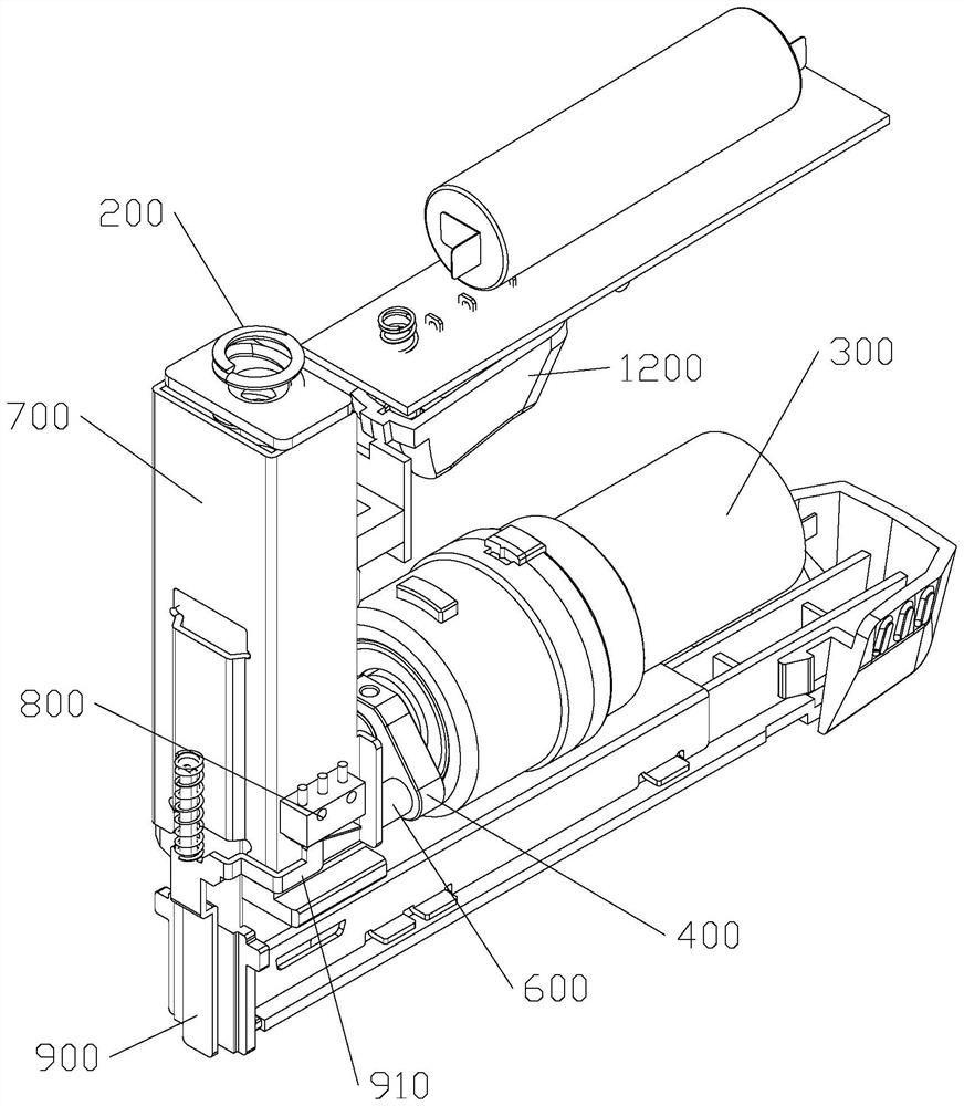
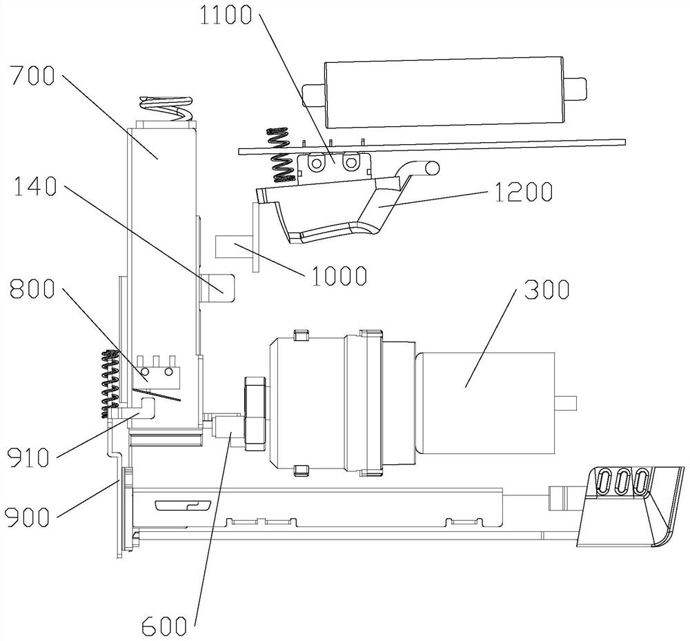
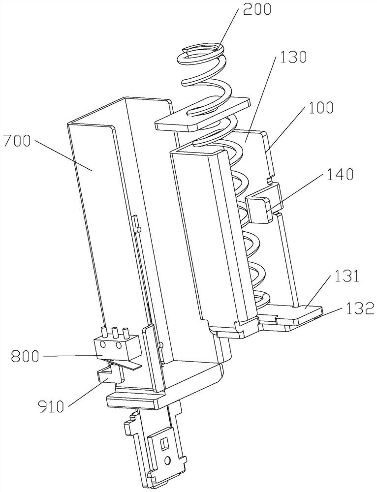
[0038] refer to Figure 1 to Figure 8 As shown, the electric nail gun in this preferred embodiment includes a housing (not shown in the figure), and a vertically sliding hammer 100, an elastic element 200 and a driving device are arranged in the housing, and the hammer 100 is installed with a Nailed stamping, the elastic element 200 is a spring, the driving device includes a motor 300, a transmission disc 400 and a transmission pin protruding from the transmission disc 400, the ...


PUM


Abstract

The low-cost electric nail gun solves the technical problem that in the prior art, an electric nail gun is high in cost and comprises a shell, and a punch hammer, an elastic element and a driving device used for driving the punch hammer to move to the high position and compressing the elastic element are arranged in the shell. The driving device comprises a motor, a transmission disc and a transmission pin arranged on the transmission disc in a protruding mode, the motor comprises a machine shell and a motor shaft connected with the transmission disc, the motor drives the transmission disc to rotate so that the transmission pin can push the punch hammer to move, a deep groove ball bearing is arranged between the motor shaft and the machine shell, and the punch hammer is provided with a step face which comprises a high face and a low face. The transmission pin comprises a first pin rod and a second pin rod which are distributed in a radial staggered mode, the distance between the first pin rod and a rotating shaft of the transmission disc is smaller than the distance between the second pin rod and the rotating shaft of the transmission disc, the peripheral side of the first pin rod or the peripheral side of the second pin rod is provided with a plane used for supporting the step face, and when the punch hammer is located at the high position, the first pin rod supports the high face. The second pin rod supports the low surface.

Description

【Technical field】 [0001] The invention relates to the technical field of nail guns, in particular to a low-cost electric nail gun. 【Background technique】 [0002] The electric nail gun in the prior art includes a casing, and a punching assembly, an elastic element and a driving device are arranged in the casing, and the driving device includes a motor, a transmission mechanism and a rotating disk, and the motor shaft of the motor is connected to the rotating disk through a transmission mechanism. There is a convex pin on the rotating disk, and the punching plate assembly includes a punching hammer and a punching plate installed on the punching hammer for punching nails. When the motor drives the rotating disk to rotate through the transmission mechanism, the convex pin moves from the low position to the high position. During the process, the protruding pin will push the hammer to a high position and compress the elastic element. After the motor drives the rotating disc to ro...

Claims


Application Information

Patent Timeline
IPC IPC(8): B25C1/06
Inventor 潘建伟严国民
Owner HANGZHOU KELONG ELECTRICAL APPLIANCE TOOLS
Learn More