
Eureka
For R&D, Eureka makes reading and utilizing patents & technical documents easy.
Eureka AIR
Designed for self-driven R&D workflows. Generate viable solutions, solve complex R&D challenges, empower your innovation with AI.

Eureka Materials
Designed for material experts only. Revolutionize your material R&D, from search, analyze, to developing new materials.

TechResearch
Generate reliable direction feasibility study reports for your R&D in just a few steps.

TechSeek
Discover and master advanced knowledge NOW. Basics, ideas, possibilities, all at once.

TechMind
As an expert in R&D Theories, TechMind can generates customized viable solutions instantly.

TechRisk
Analyze your overall solution with one click, know your potential R&D risks in advance.

TechMonitor
Get weekly tech updates, stay abreast of the latest tech innovations and key insights.
Sewage tank collecting device for sewage inspection
The technology of a collection device and a sewage tank is applied in the field of sewage tank collection devices for sewage inspection, and can solve the problems of increasing labor intensity of users, shaking of the collection tank, and laboriousness.
- Summary
- Abstract
- Description
- Claims
- Application Information
AI Technical Summary
Problems solved by technology
Method used
Image

Examples
Embodiment 1
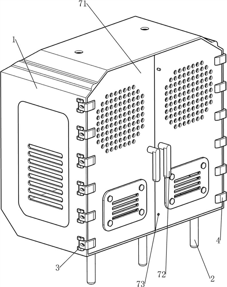
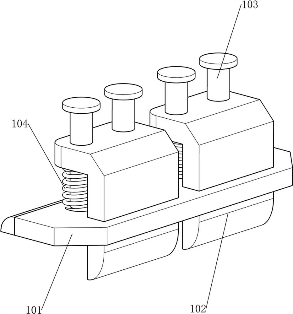
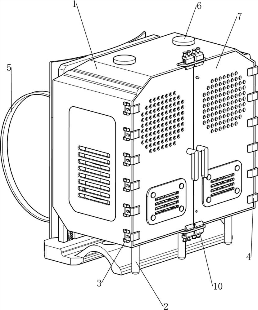
[0074] A sewage tank collection device for sewage inspection, such as Figure 1-7 As shown, it includes a frame 1, a support rod 2, a fixed block 3, a thin rotating plate 4, a booster mechanism 5 and a collection mechanism 6. Three support rods 2 are arranged on the front side of the bottom of the frame 1, and the upper parts of the left and right sides of the frame 1 are Be provided with fixed block 3, the quantity of fixed block 3 is twenty-four, the fine rotating plate 4 that is connected with rotation between the two fixed blocks 3 that are close to each other, frame 1 rear portion is provided with booster mechanism 5, and frame 1 is provided with There are collection agencies6.
[0075] When the sewage inspection needs to be collected with a sewage tank, this device can be used. The user holds up the booster mechanism 5 and puts it on the back. The mechanism 6 moves to the back, and then the user puts the booster mechanism 5 on his back to go to the place where the sewag...
Embodiment 2
[0081] On the basis of Example 1, such as Figure 8-15 As shown, the opening and closing mechanism 7 is also included, and the opening and closing mechanism 7 includes an orifice rod 71, a rotating handle 72, a large rotating plate 73, a limit block 74, a first torsion spring 75, a pull cord 76 and a winding wheel 77 , orifice rods 71 are connected between the six vertical thin rotating plates 4, and the two orifice rods 71 are connected to the frame 1 in a rotational manner, and the upper and lower parts of the right orifice rod 71 are rotatably provided with a large rotation Plate 73, the upper and lower sides of the left side of the orifice bar 71 on the right side are provided with limit blocks 74, and the upper left side of the orifice bar 71 on the right side is rotatably provided with a rotary handle 72, and the large rotation of the same side Plate 73 is rotationally connected with the limit block 74 on the same side, and the upper left side of the rear side of the...
PUM
 Abstract
Description
Claims
Application Information
 - R&D Engineer
- R&D Manager
- IP Professional
- Industry Leading Data Capabilities
- Powerful AI technology
- Patent DNA Extraction
Browse by: Latest US Patents, China's latest patents, Technical Efficacy Thesaurus, Application Domain, Technology Topic, Popular Technical Reports.
© 2024 PatSnap. All rights reserved.Legal|Privacy policy|Modern Slavery Act Transparency Statement|Sitemap|About US| Contact US: help@patsnap.com