Permeable concrete brick and pavement
A technology of permeable concrete and concrete, applied to pavement details, pavements paved with prefabricated blocks, roads, etc., to achieve the effect of reducing processing steps, reducing production costs, and increasing drainage capacity
- Summary
- Abstract
- Description
- Claims
- Application Information
AI Technical Summary
Problems solved by technology
Method used
Image
Examples
Embodiment 1
[0056] documented a paved road surface such as Figure 8 with Figure 4 shown, which includes:
[0057] a gravel layer 15 laid on the surface of the ground 18; and,
[0058] Permeable concrete bricks; the permeable concrete bricks are laid on the crushed stone layer 15, and a permeable gap is arranged between adjacent permeable concrete bricks, and the permeable gap is used for surrounding the adjacent brick matrix 1 Drain cavity 9 for drainage.
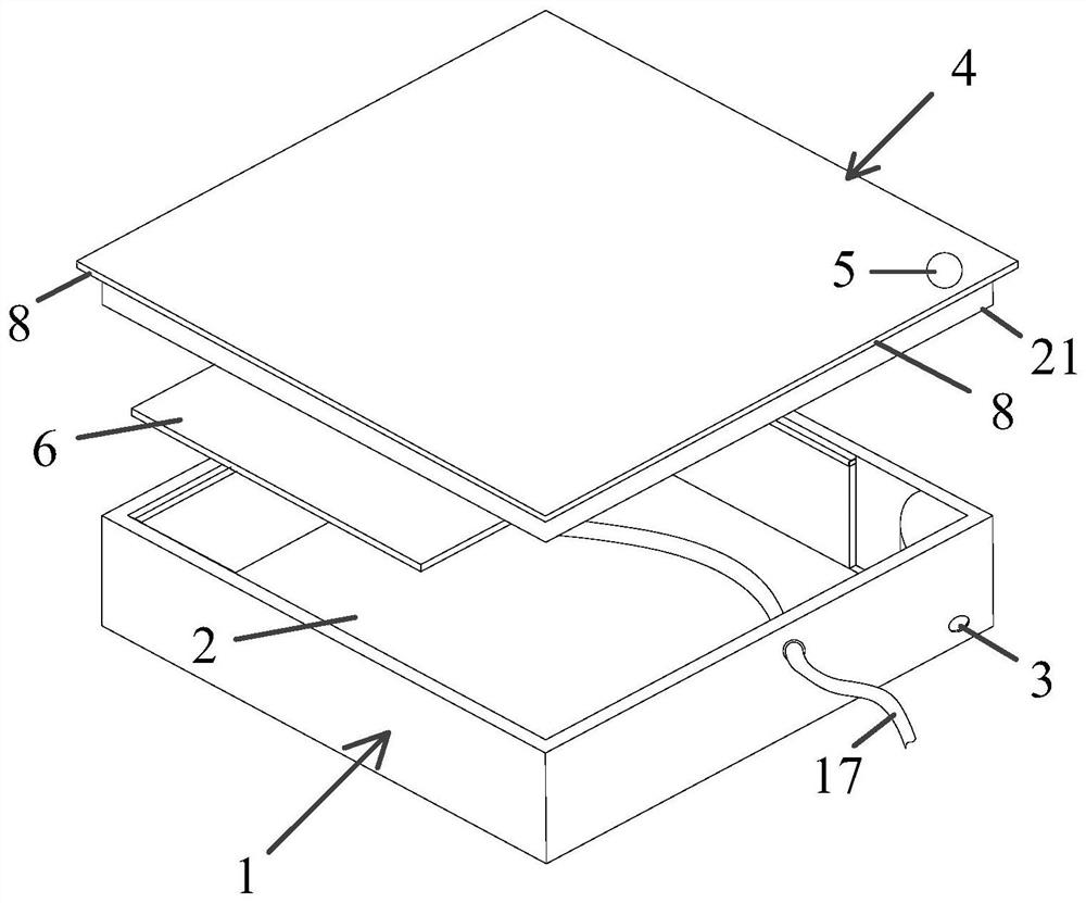
[0059] The above-mentioned permeable concrete bricks, such as figure 1 shown, which includes:
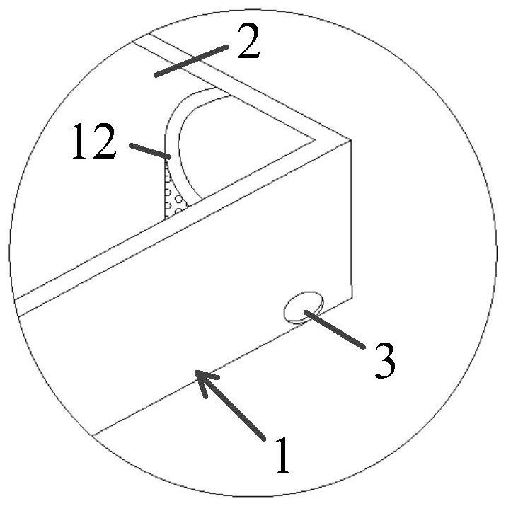
[0060] A brick base 1, the brick base 1 is made of concrete water-permeable material and has an accommodating cavity 2 for holding water, the brick base 1 is an accommodating tank with an open upper end and a closed lower end, and the brick base 1 has on its side wall A drain port 3 for drainage, the drain port 3 is located at the bottom of the chamber 2 and connected to the bottom of the chamber; by setting the drain port 3 at the bo...
Embodiment 2
[0072] The difference between this embodiment and embodiment 1 is that, as Figure 5 with Image 6 As shown, the brick cover 4 has a first extension 8 that extends out of the outer contour of the brick base 1, and the length of the first extension 8 extending toward the other brick base 1 is 4 mm; the brick The bottom surface of the base body 1 also has a second extension 14 extending toward the direction of another brick base 1 adjacent to it; One surrounds the drainage cavity 9, and a width of 2 mm is provided between two adjacent second extension parts 14. The above structure is suitable for cities with less rainfall. By arranging the second extension 14 on the outer contour edge of the bottom surface of the brick matrix 1, the speed of rainwater infiltrating into the drainage cavity 9 surrounded by the adjacent brick matrix 1 and flowing into the ground can be effectively slowed down.
[0073] Of course, this embodiment does not specifically limit the length of the firs...
Embodiment 3
[0075] The difference between this embodiment and Embodiment 1 is that the brick base 1 is made of concrete water-permeable material and has an accommodating cavity 2 for holding water, the brick base 1 is an accommodating tank with an open upper end and a closed lower end, and the brick The base body 1 has a drain outlet 3 on its side wall for draining the rainwater in the accommodating chamber 2 , and the drain outlet 3 is a strip-shaped hole extending along the height direction of the brick base body 1 . The strip-shaped hole can effectively increase the drainage capacity of the brick matrix 1,
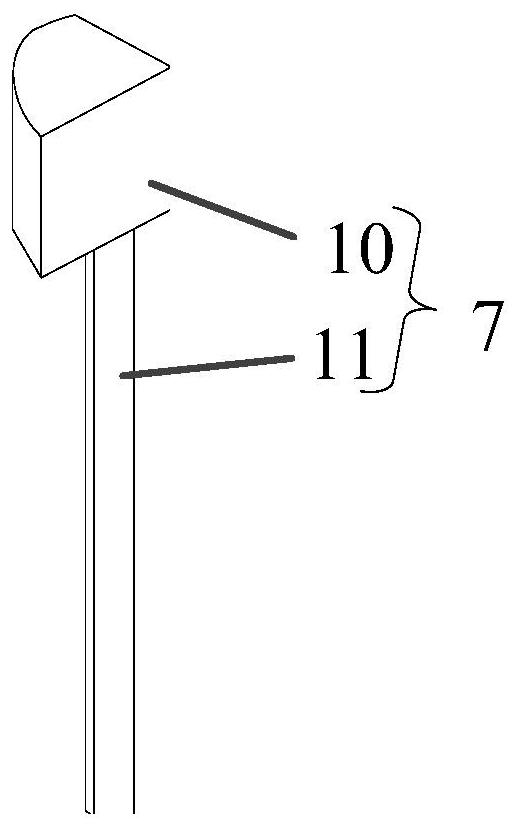
[0076] The baffle piece 11 will gradually increase the exposed part of the strip hole during the floating process, thereby improving the drainage capacity of the permeable concrete brick 16, and avoiding the fact that when the drainage port 3 is set as a round hole, the drainage capacity of the round hole is insufficient. question. Moreover, it is also possible to make the volume ...
PUM
 Abstract
Description
Claims
Application Information
 - R&D
- Intellectual Property
- Life Sciences
- Materials
- Tech Scout
- Unparalleled Data Quality
- Higher Quality Content
- 60% Fewer Hallucinations
Browse by: Latest US Patents, China's latest patents, Technical Efficacy Thesaurus, Application Domain, Technology Topic, Popular Technical Reports.
© 2025 PatSnap. All rights reserved.Legal|Privacy policy|Modern Slavery Act Transparency Statement|Sitemap|About US| Contact US: help@patsnap.com


