Safe and efficient unloading container

A technology for containers and unloading boxes, which is applied in the field of safe and efficient unloading of containers, and can solve problems such as high labor intensity, inability to realize self-unloading, and low utilization rate of monorail cranes

Pending Publication Date: 2022-04-12
HUAIBEI MINING IND
View PDF0 Cites 0 Cited by
  • Summary
  • Abstract
  • Description
  • Claims
  • Application Information

AI Technical Summary

Problems solved by technology

[0002] Usually the hoisting machinery consists of a lifting mechanism (to move the object up and down), a running mechanism (to move the hoisting machinery), a luffing mechanism and a slewing mechanism (to make the object move horizontally), plus a metal mechanism, power device, and manipulation control. It is combined with the necessary auxiliary devices. The existing spreader for container unloading includes the upper frame and the rotary lock arranged inside the upper frame. The fixed position of the rotary lock is above the bottom plane of the upper frame, and there is a certain distance from the bottom plane of the upper frame. Therefore, when lifting the container, appropriate space should be reserved around the container to accommodate the two sides of the upper frame (the two sides below the rotation lock), so that the rotation lock can be connected with the top corner of the container. Matching, lock the container on the upper frame, the diesel monorail crane uses the container to load materials, the upper edge of the container is 800mm away from the lower edge of the monorail beam, and the unloading lifting angle is 16°. When unloading yellow sand, cement and other materials, it cannot realize automatic Unloading, if complete self-unloading needs to be turned over, the safety factor is low and there are potential safety hazards. This unloading method has been eliminated
Currently, manual unloading is used for the remaining part after self-unloading. Manual unloading accounts for 2 / 3 of the container, 3-4 people need to unload, and it takes 1-2 hours. The labor intensity is high and the utilization rate of the monorail crane is low.

Method used


Image

  • Safe and efficient unloading container
  • Safe and efficient unloading container
  • Safe and efficient unloading container

Examples


Embodiment Construction

[0030] The technical solutions in the embodiments of the present application will be described below with reference to the drawings in the embodiments of the present application.

[0031] In order to make the purpose, technical solutions and advantages of the embodiments of the application clearer, the technical solutions in the embodiments of the application will be clearly and completely described below in conjunction with the accompanying drawings in the embodiments of the application. Obviously, the described embodiments It is a part of embodiment of this application, and is not all embodiment. Based on the implementation manners in this application, all other implementation manners obtained by persons of ordinary skill in the art without creative efforts fall within the scope of protection of this application.

[0032] Accordingly, the following detailed description of the embodiments of the application, provided in the accompanying drawings, is not intended to limit the ...


PUM


Abstract

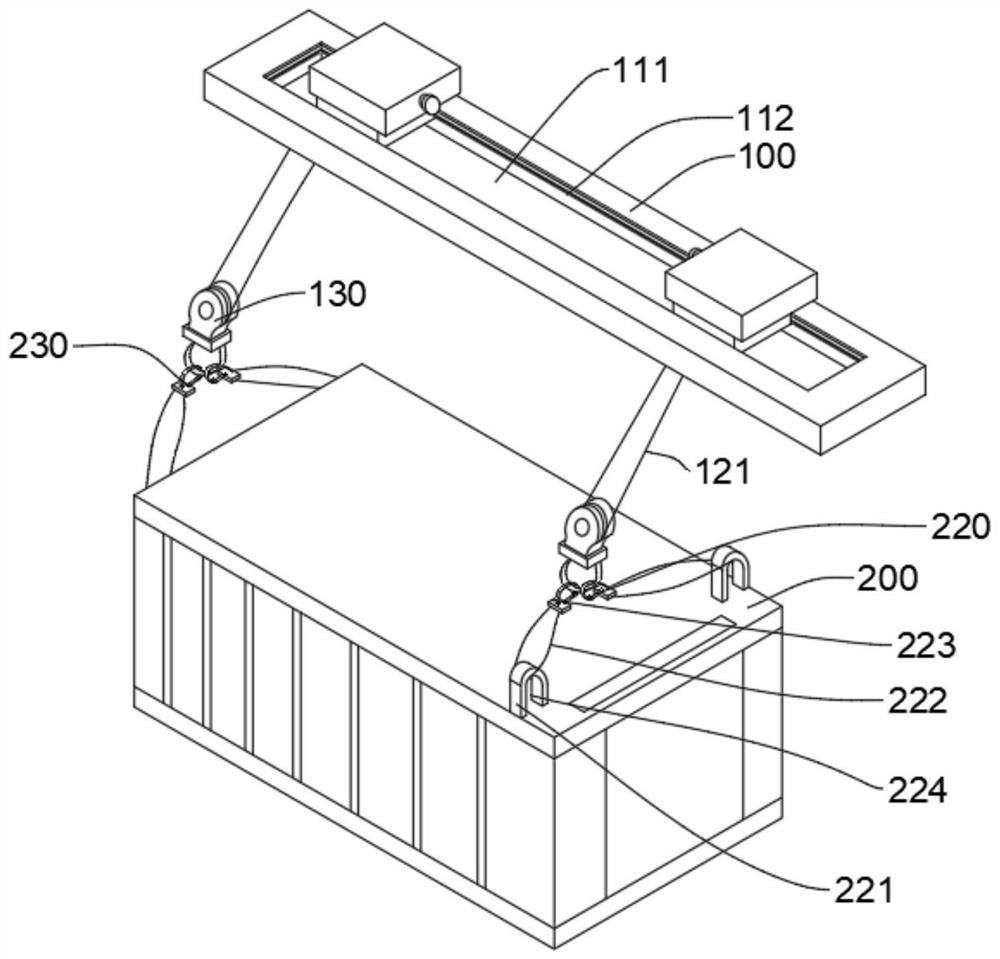
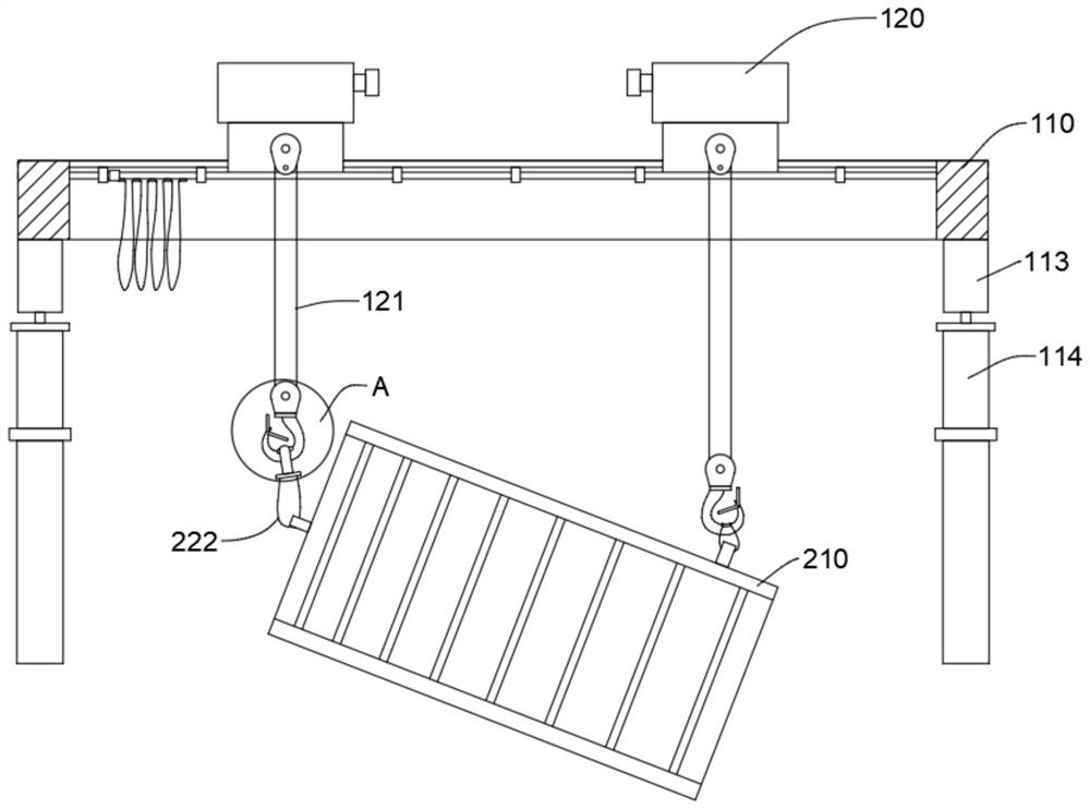
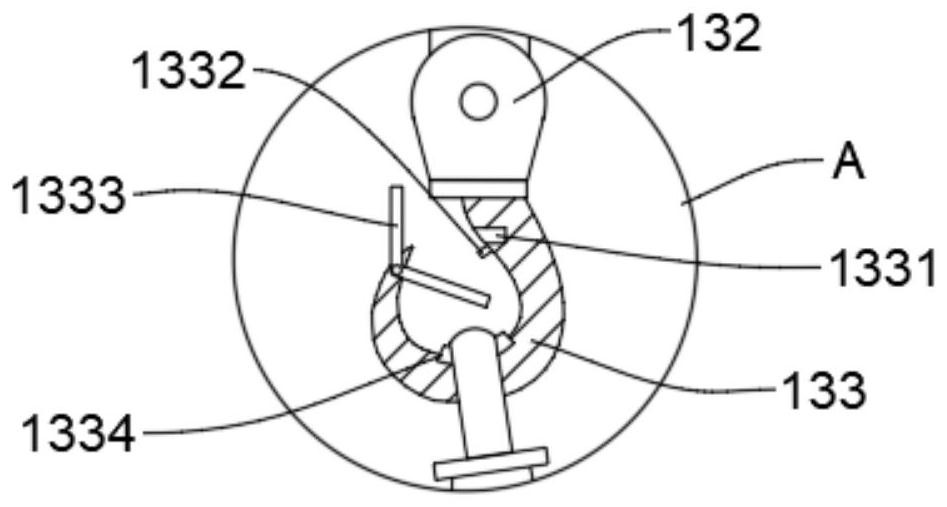
The invention provides a safe and efficient unloading container which comprises a hoisting structure and an unloading mechanism, the hoisting structure comprises a main beam and two cranes, the main beam is provided with a first sliding groove, a sliding rail is arranged in the first sliding groove, the two cranes are slidably connected to the sliding rail, and the unloading mechanism is arranged on the main beam. The two cranes penetrate through the first sliding grooves, lifting ropes are arranged at the lower ends of the two cranes, lifting appliances are connected to the lower ends of the lifting ropes, the discharging mechanism comprises a discharging box, two first connecting mechanisms are fixedly installed at one end of the discharging box, the two first connecting mechanisms are connected with the other lifting appliance, and the two first connecting mechanisms are connected with the discharging box. The other end of the unloading box is fixedly provided with two sets of second connecting mechanisms, the two sets of second connecting mechanisms are connected with the other set of lifting appliances, and the other side of the unloading box is provided with an unloading door. According to the safe and efficient unloading container, safe and efficient self-unloading can be achieved, the working efficiency is improved, and the safety is guaranteed.

Description

technical field [0001] The present application relates to the technical field of container unloading systems, in particular, to a safe and efficient unloading container. Background technique [0002] Usually the hoisting machinery consists of a lifting mechanism (to move the object up and down), a running mechanism (to move the hoisting machinery), a luffing mechanism and a slewing mechanism (to make the object move horizontally), plus a metal mechanism, power device, and manipulation control. It is combined with the necessary auxiliary devices. The existing spreader for container unloading includes the upper frame and the rotary lock arranged inside the upper frame. The fixed position of the rotary lock is above the bottom plane of the upper frame, and there is a certain distance from the bottom plane of the upper frame. Therefore, when lifting the container, appropriate space should be reserved around the container to accommodate the two sides of the upper frame (the two s...

Claims


Application Information

Patent Timeline
Patent Type & Authority Applications(China)
IPC IPC(8): B65G65/23B66C19/00B66C11/02B66C1/14B66C1/40B66C1/36B66C13/48B66C13/08
Inventor 王志刚徐杰王兴中崔保王修生桑虎李括李思昭
Owner HUAIBEI MINING IND
Why Eureka
Try Eureka