Weft insertion device of air jet loom
A technology of weft insertion device and air-jet loom, which is applied in looms, textiles, textiles, and papermaking, etc., can solve the problems of inability to completely prevent air discharge, and inability to prevent weft yarns from flying out.
- Summary
- Abstract
- Description
- Claims
- Application Information
AI Technical Summary
Problems solved by technology
Method used
Image

Examples
Embodiment approach 1
[0036] Hereinafter, Embodiment 1 of the present invention will be described in detail with reference to the drawings.
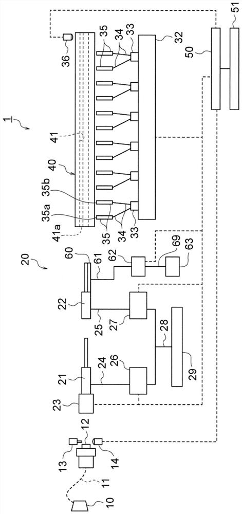
[0037] figure 1 It is a schematic diagram of the air-jet loom of Embodiment 1. The air jet loom 1 is provided with a yarn feeding device 10 for supplying a weft yarn 11 . The weft yarn 11 is drawn out by the rotation of a winding arm (not shown), and is wound up on the storage drum 12 to be stored. A weft locking pin 13 for unwinding or locking the weft yarn 11 from the storage drum 12 and a balloon sensor 14 for detecting unwinding of the weft yarn 11 from the storage drum 12 are provided near the storage drum 12 . The yarn feeding device 10, the storage drum 12, the weft yarn locking pin 13, and the balloon sensor 14 are fixed to an unillustrated frame of the air-jet loom 1 . In addition, the weft locking pin 13 and the balloon sensor 14 are connected to a main control device 50 that controls the overall operation of the air jet loom 1 . The main contro...
Embodiment approach 2
[0069] Next, the weft insertion device of the air-jet loom according to Embodiment 2 of the present invention will be described. In addition, in the following embodiments, the same as that of Embodiment 1 Figure 1 to Figure 8 The same reference numerals denote the same or similar constituent elements, and thus detailed descriptions thereof will be omitted. The weft insertion device of the air jet loom according to the second embodiment has a configuration in which the arrangement of the first main nozzle acceleration pipe 70 , the second main nozzle acceleration pipe 71 , and the guide nozzle acceleration pipe 64 is changed from that of the first embodiment.
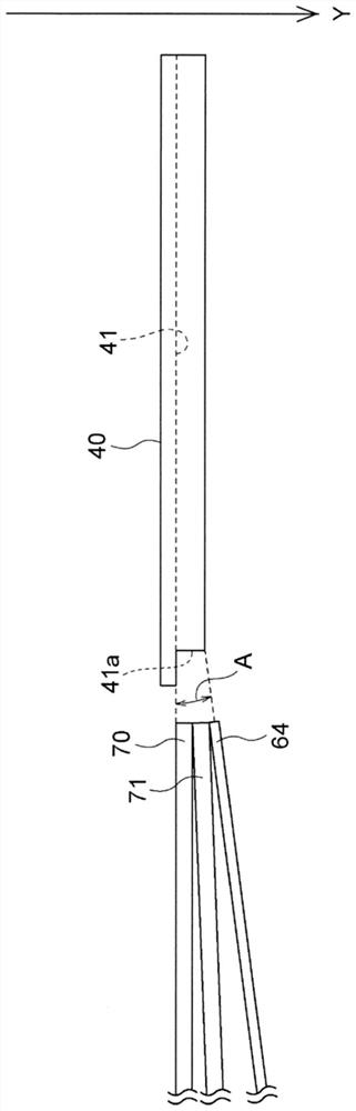
[0070] Figure 9 ~ Figure 11 It is a schematic side view when the outlets of the first main nozzle accelerating pipe 70 , the second main nozzle accelerating pipe 71 , and the pilot nozzle accelerating pipe 64 arranged differently from those in the first embodiment are viewed from the profiled reed 40 side. exist Fi...
Embodiment approach 3
[0076] Next, the weft insertion device of the air-jet loom according to Embodiment 3 of the present invention will be described. Compared with Embodiment 1, the weft insertion device of the air-jet loom according to Embodiment 3 has a structure in which the main nozzle is changed to a main nozzle having a main nozzle acceleration tube corresponding to six-color weft yarns.
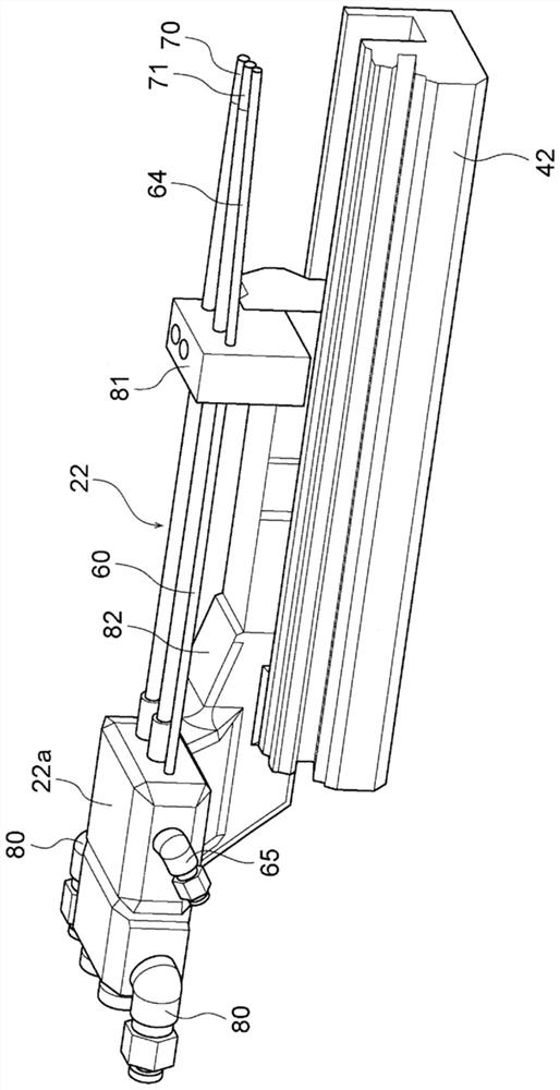
[0077] Figure 12 is a schematic diagram of the main nozzle 22 and the pilot nozzle 60 . The main nozzle 22 is a 6-color main nozzle that sends out 6-color weft yarns, and has: a main nozzle base 22a, a first main nozzle acceleration tube 70 and a second main nozzle acceleration tube respectively arranged on the main nozzle base 22a corresponding to the color of the weft yarn. 71. The third main nozzle accelerating pipe 72, the fourth main nozzle accelerating pipe 73, the fifth main nozzle accelerating pipe 74, and the sixth main nozzle accelerating pipe 75. In addition, the first main nozzle acceleratin...
PUM
 Abstract
Description
Claims
Application Information
 - R&D Engineer
- R&D Manager
- IP Professional
- Industry Leading Data Capabilities
- Powerful AI technology
- Patent DNA Extraction
Browse by: Latest US Patents, China's latest patents, Technical Efficacy Thesaurus, Application Domain, Technology Topic.
© 2024 PatSnap. All rights reserved.Legal|Privacy policy|Modern Slavery Act Transparency Statement|Sitemap