Support for positioning reinforcement cage segments

A steel cage and segment technology, which is used in the erection/assembly of bridges, bridge parts, sheet pile walls, etc., can solve the problems of difficult connection and alignment of steel cage segments, disturbance and deformation of steel bars, etc. Integrity and stiffness, the effect of convenient hand-held operation

Pending Publication Date: 2022-04-12
四川路航建设工程有限责任公司
View PDF0 Cites 0 Cited by
  • Summary
  • Abstract
  • Description
  • Claims
  • Application Information

AI Technical Summary

Problems solved by technology

[0005] The object of the present invention is to provide a support for the positioning of the reinforcement cage segments in view of the problem in the prior art that the vertical reinforcement t

Method used


Image

  • Support for positioning reinforcement cage segments
  • Support for positioning reinforcement cage segments
  • Support for positioning reinforcement cage segments

Examples


Embodiment 1

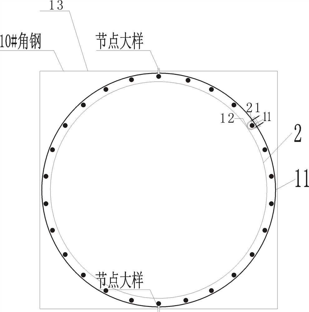
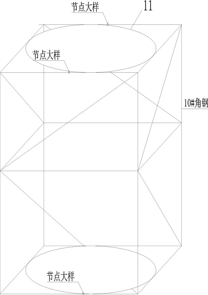
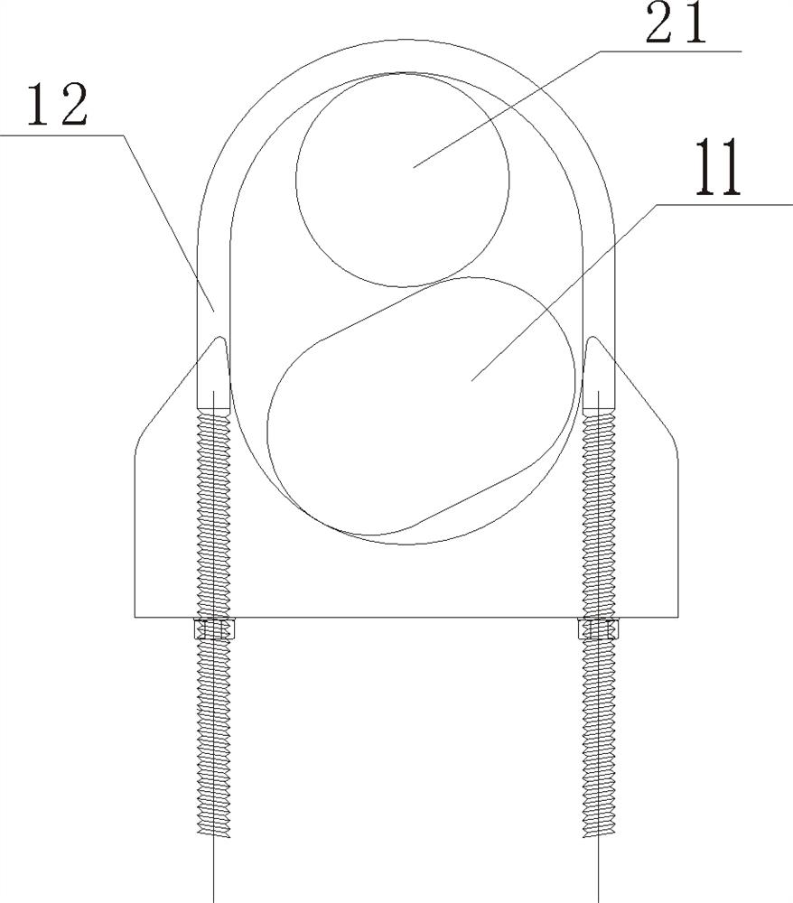
[0032] Embodiment 1: A bracket for positioning steel cage segments, as shown in the figure, includes a ring piece 11, the ring piece 11 is a split structure, and the ring piece 11 includes at least two sections of arc-shaped units, which are convenient for installation and disassembly; The member 11 is provided with positioning members 12 at intervals in the circumferential direction, and the positioning members 12 are used for detachably connecting each longitudinal steel bar 21 in the reinforcement cage.

[0033] The support for segmental positioning of the reinforcement cage provided in this embodiment is the size of the ring member determined according to the circumference of the reinforcement cage to be positioned, and the positioning member on the ring member is set according to the number of longitudinal reinforcement bars on the reinforcement cage and the preset spacing. Quantity and position, so that the ring parts can be set on the inside or outside of the steel cage,...

Embodiment 2

[0046] Embodiment 2: Based on the above embodiment, the above-mentioned ring member can be arranged as an integrally formed structure, which can be arranged inside or outside the reinforcement cage. During the production of the reinforcement cage, the end of the longitudinal reinforcement is directly bound through the ring piece and the positioning piece at the corresponding position, and the reinforcement cage is formed; When there is no disturbing deformation in the process or the disturbing deformation is small enough, the ring piece is pulled out from the connecting end of the steel cage, and it is docked with the steel cage segment that also ensures that the longitudinal steel bar is in place, so as to solve the problem of longitudinal steel bar misalignment and deformation. Alternatively, the ring is placed inside the reinforcement cage and poured together with the reinforcement cage.

[0047] Reinforcement cage installation process (such as Figure 7-Figure 8 ): (1) Af...


PUM


Abstract

The invention relates to a support for positioning reinforcement cage segments, which comprises an annular piece, the annular piece comprises at least two arc units, and positioning pieces are arranged on the annular piece at intervals in the circumferential direction and are used for detachably connecting longitudinal reinforcements in a reinforcement cage. The support for positioning the reinforcement cage sections can be used for hoisting together with the reinforcement cage, the integrity and rigidity of the reinforcement cage sections in the hoisting link are improved, and the situation that alignment connection is affected due to disturbance deformation of longitudinal reinforcements in the hoisting process of the reinforcement cage is prevented. Longitudinal steel bars can be rapidly and accurately positioned, aerial butt joint of steel reinforcement cage sections can be rapidly completed, and the steel reinforcement cage can be repeatedly used.

Description

technical field [0001] The invention relates to the technical field of reinforcement cage construction, in particular to a support for segmental positioning of a reinforcement cage. Background technique [0002] Reinforcement cages for high bridge piers and long pile foundations are generally constructed using segmental connections. Reinforcement cages are fabricated in segments in the reinforcement processing plant (including multiple longitudinal reinforcements and hoop stirrups), and then the reinforcement cage segments are transported to the construction site. Restricted by the height limit of the crane and the length of the transport vehicle, the steel cage segments need to be butted and installed in the air. [0003] Since the reinforcement cage is generally manufactured and shaped in the reinforcement processing plant, it is transported to the site for installation. The original design of the shaped reinforcement cannot guarantee the deformation and dislocation of th...

Claims


Application Information

Patent Timeline
IPC IPC(8): E02D5/34E02D27/12E02D15/08E01D19/02E01D21/00
Inventor 孙密张军陈勇蒋华斌陶滔罗连红杨威喻勇杨礼张恒白恩名李林传雷敏龙小燕
Owner 四川路航建设工程有限责任公司
Why Eureka
Try Eureka