Supercharge Your Innovation With Domain-Expert AI Agents!

Waterproof glass fiber tile mounting device

A technology of waterproof fiberglass tiles and installation devices, which is applied to tools used in roofing engineering, roofing, construction, etc., can solve problems such as low efficiency, large manpower consumption, roof leakage, etc., and achieve the effect of easy laying

Pending Publication Date: 2022-04-12
谢荣才
View PDF0 Cites 2 Cited by
  • Summary
  • Abstract
  • Description
  • Claims
  • Application Information

AI Technical Summary

Problems solved by technology

[0003] In order to overcome the shortcomings of laying waterproof fiberglass tiles manually, it takes a lot of time, consumes a lot of manpower, and the efficiency is not high, and when workers need to lay waterproof fiberglass tiles, the connection between the tiles is not tight enough, resulting in roof leakage. The invention provides a waterproof glass fiber tile installation device

Method used


Image

  • Waterproof glass fiber tile mounting device
  • Waterproof glass fiber tile mounting device
  • Waterproof glass fiber tile mounting device

Examples


Embodiment 1

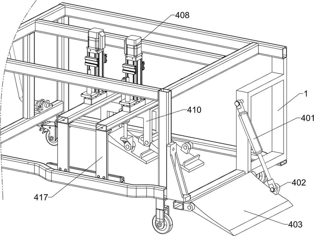
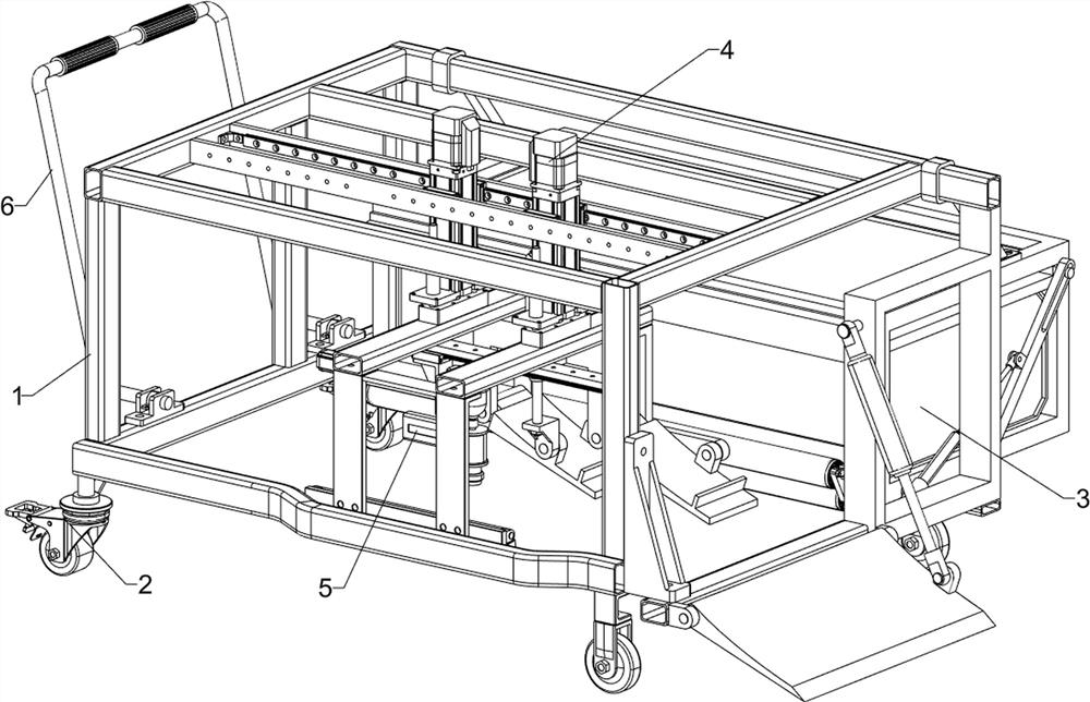
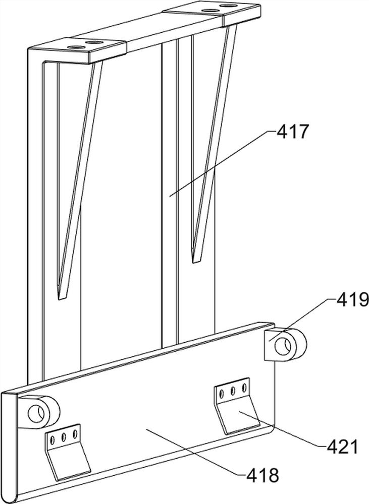
[0039] A waterproof glass fiber tile installation device, such as Figure 1-3 As shown, it includes a frame 1, wheels 2, a feeding system 3 and a laying system 4; each of the four corners of the lower surface of the frame 1 is connected with a wheel 2; the rear of the frame 1 is connected with a feeding system 3; the frame 1 A laying system 4 is connected inside; a handrail 6 is connected to the left part of the frame 1 .

[0040] Working principle: When using the waterproof fiberglass tile installation device, first place the waterproof fiberglass tile installation device on the roof where waterproof fiberglass tiles need to be laid, and then the operator puts the waterproof fiberglass tile into the feeding system 3, and then connects Turn on the built-in power supply, and then the operator pushes the waterproof glass fiber tile installation device to the corner of the roof, lays the waterproof glass fiber tile from the corner to the middle, and then controls the feeding syst...

Embodiment 2

[0042] On the basis of Example 1, such as figure 1 and Figure 4-16 As shown, the feeding system 3 includes a placement bin 301, a bracket 302, a connecting sleeve 303, a first electric push rod 304, a transmission rod 305, a first connecting seat 306, a toggle plate 307, a first guide plate 308, a second Guide plate 309, second connecting seat 310, first rotating roller 311, second rotating roller 312, first spur gear 313, second spur gear 314, first connecting plate 315, motor 316, cabin door 317, handle 318, First elastic part 319 and stage 320; Frame 1 rear portion is fixedly connected with placement bin 301; Place bin 301 upper surface right and upper surface left each bolt is connected with a bracket 302; Two brackets 302 and frame 1 phase connection; the outer right side and the outer left side of the storage compartment 301 are respectively connected with a connecting sleeve 303 through a rotating shaft; each of the two connecting sleeves 303 is fixedly connected with...

Embodiment 3

[0056] On the basis of Example 2, such as figure 1 and Figure 17 As shown, it also includes a fixing system 5; the lower surface of the two third connecting plates 409 is connected with the fixing system 5; the fixing system 5 includes a sixth connecting plate 501, a second electric slide rail 502, a second electric slider 503, The third connecting frame 504 and the pneumatic nail gun 505; the middle part of the lower surface of the two third connecting plates 409 is fixedly connected with the sixth connecting plate 501; the lower surface of the sixth connecting plate 501 is fixedly connected with the second electric slide rail 502; The outer surface of the slide rail 502 is slidably connected with a second electric slider 503; the lower surface of the second electric slider 503 is fixedly connected with a third connecting frame 504; the right part of the third connecting frame 504 is fixedly connected with a pneumatic nail gun 505.

[0057] Working principle: When two water...


PUM


Abstract

The invention relates to a waterproof glass fiber tile, in particular to a waterproof glass fiber tile mounting device. The technical problems that when waterproof glass fiber tiles are laid manually, a large amount of time and a large amount of manpower are consumed, efficiency is not high, and when workers need to lay the waterproof glass fiber tiles, connection between the tiles is not tight enough, and consequently roof water leakage is caused are solved. According to the technical scheme, the waterproof glass fiber tile mounting device comprises a rack, wheels, a feeding system and the like; four corners of the lower surface of the rack are respectively connected with a wheel; the rear part of the rack is connected with a feeding system; the feeding system is used for transferring the waterproof glass fiber tiles to a working position. The waterproof glass fiber tiles are sent out through the feeding system, the waterproof glass fiber tiles are limited through the laying system, so that the waterproof glass fiber tiles are laid on the roof straightly, the two waterproof glass fiber tiles are stacked together through the laying system, and the situation that the tiles are not tightly connected, and consequently roof water leakage is caused is prevented.

Description

technical field [0001] The invention relates to waterproof glass fiber tiles, in particular to a waterproof glass fiber tile installation device. Background technique [0002] In the prior art, the laying method of waterproof fiberglass tiles is that workers place waterproof fiberglass tiles one by one on the roof where waterproof fiberglass tiles need to be laid, and then nail them. The area of ​​waterproof fiberglass tiles on the roof is small, and it is necessary to lay a large number of waterproof fiberglass tiles on the roof to completely cover the roof. This method of laying requires workers to spend a lot of time and manpower, and the efficiency is not high. When laying waterproof fiberglass tiles, the connection between the tiles is not tight enough, which leads to water leakage on the roof. Contents of the invention [0003] In order to overcome the shortcomings of laying waterproof fiberglass tiles manually, it takes a lot of time, consumes a lot of manpower, an...

Claims


Application Information

Patent Timeline
Patent Type & Authority Applications(China)
IPC IPC(8): E04D15/02
Inventor 谢荣才
Owner 谢荣才
Features
  • R&D
  • Intellectual Property
  • Life Sciences
  • Materials
  • Tech Scout
  • Unparalleled Data Quality
  • Higher Quality Content
  • 60% Fewer Hallucinations
Learn More