Pressing force adjusting assembly of plunger type hydraulic element

A technology of hydraulic components and adjustment components, which is applied in the field of hydraulic components, can solve the problems of inability to change, too large matching gap between the valve plate and the plunger cylinder, and reduced volumetric efficiency, so as to achieve the effect of maintaining balance

Active Publication Date: 2022-04-12
靖江艾威机械配件制造有限公司
View PDF6 Cites 0 Cited by
  • Summary
  • Abstract
  • Description
  • Claims
  • Application Information

AI Technical Summary

Problems solved by technology

The remaining pressing force coefficient has a great influence on the performance of the distribution pair. If the remaining pressing force coefficient is too large, the friction between the valve plate and the plunger cylinder will increase, the mechanical efficiency will decrease, and even "burning" will occur; if the remaining pressing force coefficient If the coefficient of tightening force is too small, the gap between the valve plate and the plunger cylinder will be too large, resulting in increased leakage and reduced volumetric efficiency. According to the current design method, the remaining pressure coefficient depends on the diameter of the plunger and the waist hole of the valve plate, etc. Therefore, after the radial piston pump and other components are finalized, the remaining pressing force coefficient will not be changed, which will seriously affect the lubrication characteristics of the flow distribution pair and the overall efficiency of the radial piston pump and other components

Method used


Image

  • Pressing force adjusting assembly of plunger type hydraulic element
  • Pressing force adjusting assembly of plunger type hydraulic element
  • Pressing force adjusting assembly of plunger type hydraulic element

Examples


Embodiment

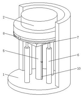
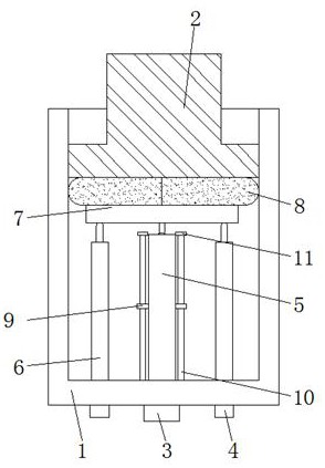
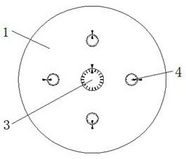
[0031] Example: refer to Figure 1-7 , the pressing force adjustment assembly of the plunger type hydraulic element, including the connection housing 1 and the piston rod 2, the bottom of the connection housing 1 is connected with the first adjustment knob 3 and the second adjustment knob 4, and one end of the first adjustment knob 3 The pressing force adjustment assembly 5 is connected and installed through the connection housing 1, and one end of the second adjustment knob 4 is connected and installed with the balance adjustment assembly 6 through the connection housing 1, and the top end of the pressing force adjustment assembly 5 is connected and installed with a contact base 7, And the top of the balance adjustment assembly 6 is connected to the contact base 7, the contact piece 8 is slidingly connected to the top of the contact base 7, and the top of the contact piece 8 is connected to the bottom of the piston rod 2, and both sides of the pressing force adjustment assembl...


PUM


Abstract

The invention relates to the technical field of hydraulic elements, in particular to a pressing force adjusting assembly of a plunger type hydraulic element, which comprises a connecting shell and a piston rod, the bottom of the connecting shell is rotatably connected with a first adjusting knob and a second adjusting knob, one end of the first adjusting knob is connected with the pressing force adjusting assembly through the connecting shell, and the other end of the first adjusting knob is connected with the piston rod. One end of the second adjusting knob is connected with a balance adjusting assembly through a connecting shell, the top end of the pressing force adjusting assembly is connected with a contact base, the top end of the balance adjusting assembly is connected with the contact base, the top end of the contact base is slidably connected with a contact piece, and the top end of the contact piece is connected with the bottom of a piston rod. Connecting plates are fixedly mounted on the two sides of the pressing force adjusting assembly correspondingly, and two guide rods are fixedly mounted on the inner wall of the bottom of the connecting shell. According to the pressing device, the pressing force can be adjusted, meanwhile, the balance of the piston rod can be adjusted, and the pressing device is very practical.

Description

technical field [0001] The invention relates to the technical field of hydraulic components, in particular to a pressing force adjustment assembly of a plunger type hydraulic component. Background technique [0002] Plunger hydraulic components mainly include axial piston pumps (motors), floating cup hydraulic pumps (motors) and hydraulic transformers based on the former two. Tension coefficient design principles. The remaining pressing force coefficient has a great influence on the performance of the distribution pair. If the remaining pressing force coefficient is too large, the friction between the valve plate and the plunger cylinder will increase, the mechanical efficiency will decrease, and even "burning" will occur; if the remaining pressing force coefficient If the coefficient of tightening force is too small, the gap between the valve plate and the plunger cylinder will be too large, resulting in increased leakage and reduced volumetric efficiency. According to the...

Claims


Application Information

Patent Timeline
Patent Type & Authority Applications(China)
IPC IPC(8): F15B15/14F15B15/20F16F15/067
Inventor 钱皎
Owner 靖江艾威机械配件制造有限公司
Why Eureka
Try Eureka