
Large-span arch rib temporary buttress reverse pre-pressing detection method

A temporary buttress and detection method technology, which is applied in the direction of measuring devices, strength characteristics, and the use of stable tension/pressure test material strength, etc., can solve the problems of lack of detection methods such as bracket pre-compression detection

Pending Publication Date: 2022-04-12
CR10BG NO 3 CONSTR +2
View PDF7 Cites 0 Cited by
  • Summary
  • Abstract
  • Description
  • Claims
  • Application Information

AI Technical Summary

Problems solved by technology

[0003] Since the support is temporarily built, before it is put into use, it is necessary to conduct a vertical compressive static load test on the temporarily built support to determine the vertical compressive ultimate bearing capacity and elastic deformation of the support to ensure that it can support the arch rib; However, in the prior art, there is a lack of a better detection method to detect the preloading of the stent

Method used


Image

  • Large-span arch rib temporary buttress reverse pre-pressing detection method
  • Large-span arch rib temporary buttress reverse pre-pressing detection method
  • Large-span arch rib temporary buttress reverse pre-pressing detection method

Examples


Embodiment 1

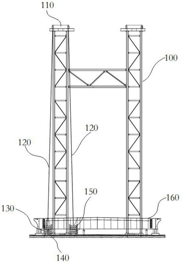
[0030] Such as Figure 1~2 As shown, this embodiment provides a method for detecting reverse preloading of temporary buttresses with large-span arch ribs, which includes the following steps:

[0031] S1, bracket 100 selection

[0032] Select a set of supports 100 with the highest temporary supports at the mid-span of the large-span arch rib;

[0033] In the actual construction process, according to the shape of the large-span arch rib, multiple sets of brackets 100 with different heights will be temporarily built to support different arch rib sections; the detection method in this embodiment adopts the method of sampling detection, through Sampling tests are carried out on the temporary supports to evaluate the bearing capacity of the temporary supports. In this embodiment, the highest set of supports 100 are selected for preload testing;

[0034] S2, distribution beam 110 installation

[0035] Install the distribution beam 110 at the highest point of the bracket 100 select...

Embodiment 2

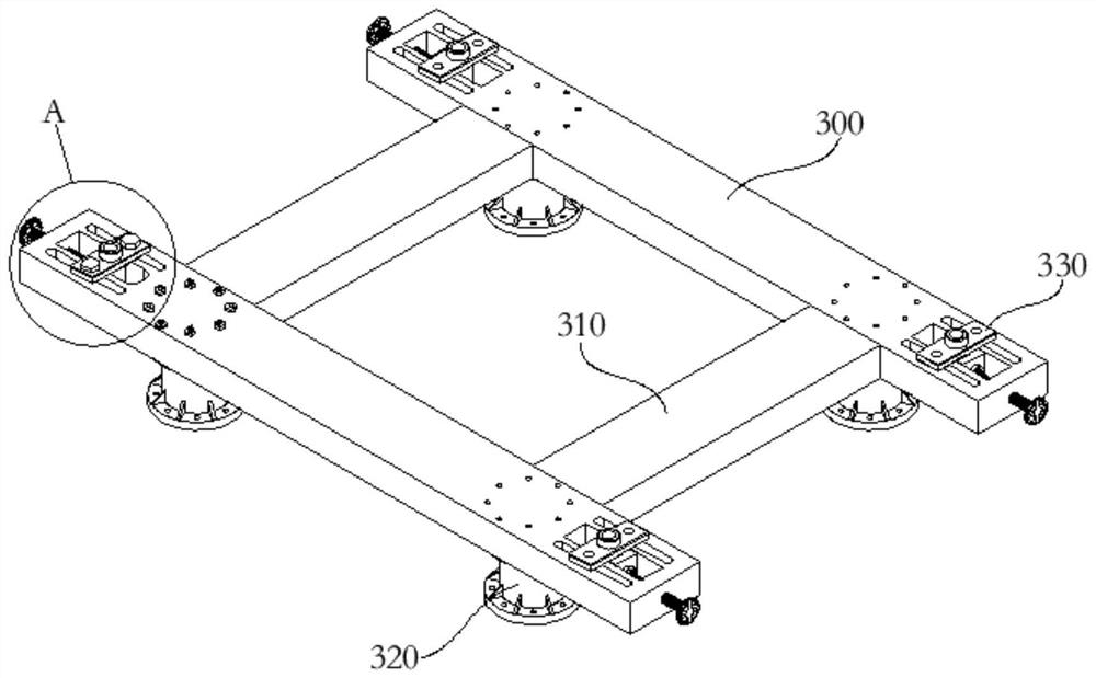
[0054] This embodiment provides a distribution beam, which is used to realize the installation of the distribution beam at the highest position of the support in Embodiment 1.

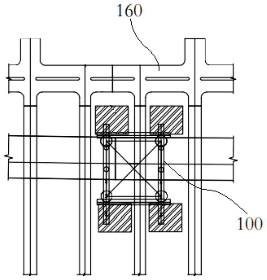
[0055] Such as image 3 As shown, in this embodiment, the distribution beam includes support plates 300 arranged in parallel, and the support plates 300 are connected by connecting plates 310. The lower plate surface of the support plate 310 is provided with a support column 320 connected to the uppermost end of the bracket 100, Both ends of the supporting column 320 are provided with a connecting flange 410, and the connecting flange 410 is connected to the corresponding supporting plate 310 and the support 100 by bolts; Anchors 330 .

[0056] In this embodiment, the connection plate 310 is connected to the support plate 300 by welding, so that the support plate 300 and the connection plate 310 form a structure that is compatible with the uppermost end of the bracket 120, wherein one end of the suppo...


PUM


Abstract

The invention relates to the technical field of bridge construction, in particular to a large-span arch rib temporary buttress reverse pre-pressing detection method which comprises the following steps: S1, support selection; s2, mounting a distribution beam; s3, steel strand installation; s4, mounting a hanging basket; s5, the saddle weight is placed; and S6, jack adjustment. According to the pre-pressing detection method, a test method close to the actual working stress of a temporary support is adopted, the stress condition and deformation characteristics of the support are accurately reflected, the vertical compression bearing capacity of the support is determined, and meanwhile the detection method is easy to operate and good in detection effect.

Description

technical field [0001] The invention relates to the technical field of bridge construction, in particular to a detection method for reverse preloading of temporary buttresses with large-span arch ribs. Background technique [0002] During the actual construction of long-span arch bridges, temporary piers need to be built to support the arch ribs and assist the construction of the arch ribs. In the prior art, the temporary buttresses are usually temporarily erected supports of different heights, and the supports of different heights are used to support different arch rib sections to assist in the closing construction of the arch ribs. [0003] Since the support is temporarily built, before it is put into use, it is necessary to conduct a vertical compressive static load test on the temporarily built support to determine the vertical compressive ultimate bearing capacity and elastic deformation of the support to ensure that it can support the arch rib; However, in the prior a...

Claims


Application Information

Patent Timeline
IPC IPC(8): G01N3/14G01N3/02
Inventor 杨帆李健高虎孙伟李栋
Owner CR10BG NO 3 CONSTR
Features
  • Generate Ideas
  • Intellectual Property
  • Life Sciences
  • Materials
  • Tech Scout
  • Unparalleled Data Quality
  • Higher Quality Content
  • 60% Fewer Hallucinations
Learn More