Optical module aging device

An aging device and optical module technology, applied in the field of optical communication, can solve the problems of large heat generation, easy over-temperature, poor temperature uniformity, etc., and achieve the effect of uniform temperature, ensuring temperature uniformity, and ensuring accuracy and consistency

Pending Publication Date: 2022-04-12
STELIGHT INSTR CO LTD
View PDF0 Cites 0 Cited by
  • Summary
  • Abstract
  • Description
  • Claims
  • Application Information

AI Technical Summary

Problems solved by technology

Due to the large self-heating of the module, the temperature uniformity of the whole warehouse is poor, and it is easy to overheat (that is, the ambient temperature exceeds the temperature set by the user)

Method used


Image

  • Optical module aging device
  • Optical module aging device
  • Optical module aging device

Examples


Embodiment 1

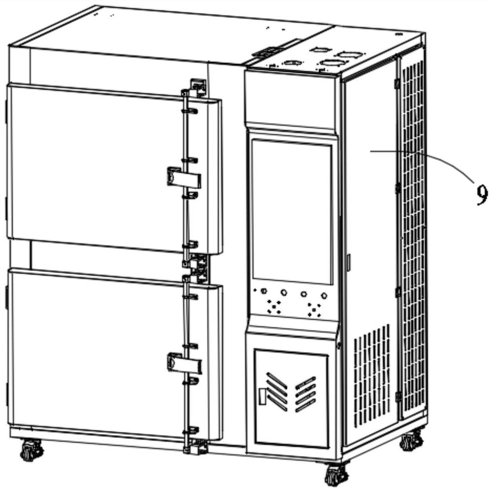
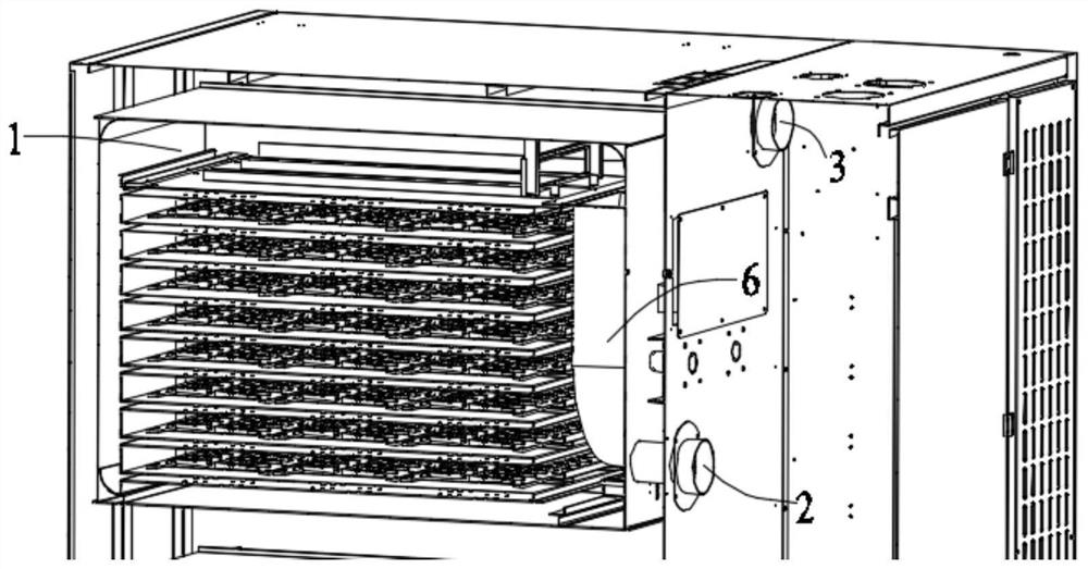
[0024] Embodiment 1: An optical module aging device, including at least one heating chamber 1, at least one air inlet 2 and at least one pressure relief port 3 are opened on the heating chamber 1, and several heating chambers are installed in the heating chamber 1 On the carrier plate 5 where the optical module 4 is placed, several carrier plates 5 are vertically spaced in the heating chamber 1, and a first cavity area is formed between the uppermost carrier plate 5 and the heating chamber 1 A centrifugal fan 6 is installed in the heating chamber 1 and located on one side of several carrier boards 5, and the other side of the several carrier boards 5 and the heating chamber 1 are surrounded by a space that communicates with the first cavity area. The second cavity area;

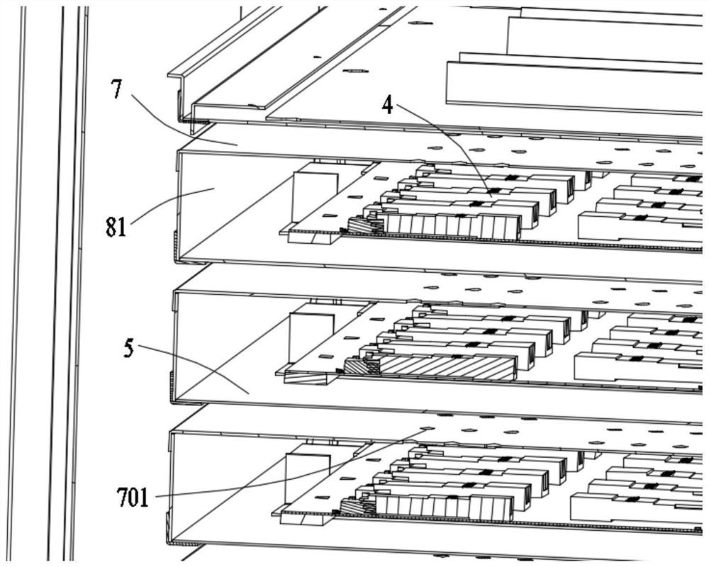
[0025] An air shower plate 7 is arranged between two adjacent carrier plates 5, and one end of the air shower plate 7 close to the second cavity area is connected with the carrier plate 5 below it through a f...

Embodiment 2

[0031] Embodiment 2: An optical module aging device, including at least one heating chamber 1, at least one air inlet 2 and at least one pressure relief port 3 are opened on the heating chamber 1, and several heating chambers are installed in the heating chamber 1 On the carrier plate 5 where the optical module 4 is placed, several carrier plates 5 are vertically spaced in the heating chamber 1, and a first cavity area is formed between the uppermost carrier plate 5 and the heating chamber 1 A centrifugal fan 6 is installed in the heating chamber 1 and located on one side of several carrier boards 5, and the other side of the several carrier boards 5 and the heating chamber 1 are surrounded by a space that communicates with the first cavity area. The second cavity area;

[0032] An air shower plate 7 is arranged between two adjacent carrier plates 5, and one end of the air shower plate 7 close to the second cavity area is connected with the carrier plate 5 below it through a f...


PUM


Abstract

An optical module aging device disclosed by the present invention comprises at least one heating bin, the heating bin is provided with at least one air inlet and at least one pressure relief port, the heating bin is internally provided with a plurality of carrier plates for placing optical modules, and the plurality of carrier plates are arranged in the heating bin along the vertical direction at intervals. A first cavity area is defined between the uppermost carrier plate and the heating bin, a centrifugal fan is installed in the heating bin and located on one side of the multiple carrier plates, and a second cavity area communicated with the first cavity area is defined between the other sides of the multiple carrier plates and the heating bin. The diameters of the air outlet holes in the air shower plates are the same, and the diameters of the air outlet holes in the upper air shower plate are larger than the diameters of the air outlet holes in the lower air shower plate between the adjacent air shower plates. The temperature uniformity of each optical module can be always kept in a multi-heat-source and large-capacity heating bin, and the temperature uniformity in the bin is actually measured to be +/-3 DEG C when the capacity of a single-bin optical module is 1248, so that the accuracy and the consistency of aging test data of the optical module are ensured.

Description

technical field [0001] The invention relates to an optical module aging device, which belongs to the technical field of optical communication. Background technique [0002] The photoelectric conversion module (referred to as the optical module) is an important component unit in the optical fiber communication system, and its main function is to complete the conversion of optical signals and electrical signals. The application scenarios of optical modules are complex, so it is necessary for optical modules to undergo high-temperature charging aging in the manufacturing environment, so as to screen out unqualified products, further prolong the service life of products and improve the pass rate of terminal use. In order to better remove defective products, optical modules need to be powered on for a period of time in a high-temperature environment before leaving the factory, so that unqualified products will be exposed to poor performance in harsh environments in advance and be...

Claims


Application Information

Patent Timeline
Patent Type & Authority Applications(China)
IPC IPC(8): G01R31/00G01R1/04
Inventor 刘伟胡海洋纪铭黄建军
Owner STELIGHT INSTR CO LTD
Why Eureka
Try Eureka