
Eureka
For R&D, Eureka makes reading and utilizing patents & technical documents easy.
Eureka AIR
Designed for self-driven R&D workflows. Generate viable solutions, solve complex R&D challenges, empower your innovation with AI.

Eureka Materials
Designed for material experts only. Revolutionize your material R&D, from search, analyze, to developing new materials.

TechResearch
Generate reliable direction feasibility study reports for your R&D in just a few steps.

TechSeek
Discover and master advanced knowledge NOW. Basics, ideas, possibilities, all at once.

TechMind
As an expert in R&D Theories, TechMind can generates customized viable solutions instantly.

TechRisk
Analyze your overall solution with one click, know your potential R&D risks in advance.

TechMonitor
Get weekly tech updates, stay abreast of the latest tech innovations and key insights.
Foot bath control method and foot bath device
A control method and footbath technology, applied to showers, program control in sequence/logic controllers, electrical program control, etc., can solve problems such as damage to the lifting device, failure of the footbath to be lifted in place, failure of the lifting device, etc.
- Summary
- Abstract
- Description
- Claims
- Application Information
AI Technical Summary
Problems solved by technology
Method used
Image

Examples
Embodiment 1
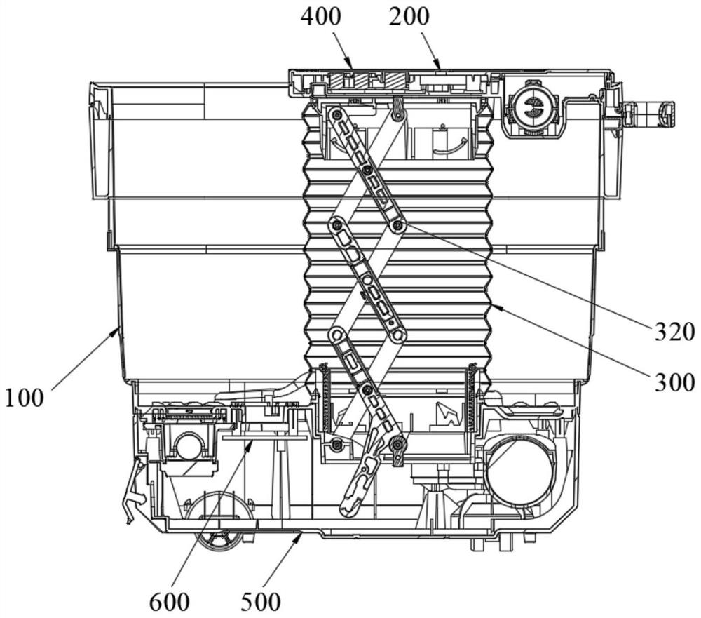
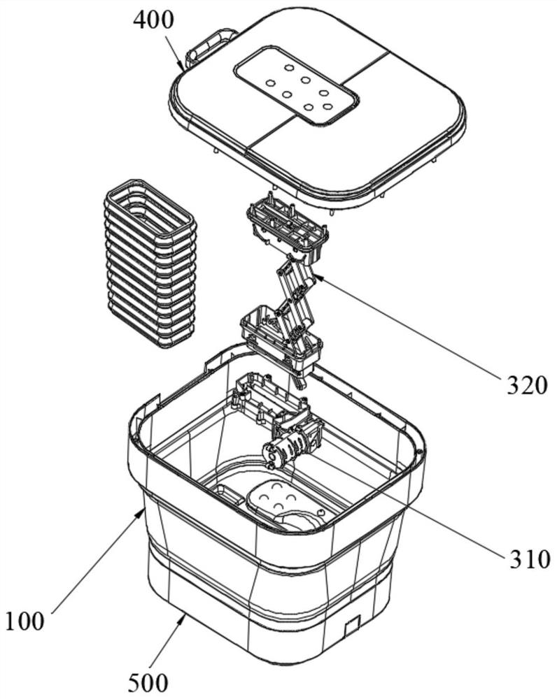
[0059] figure 1 It is a schematic structural view of the foot bath in Embodiment 1 of the present application, figure 2 It is a schematic diagram of the decomposition structure of the foot bath in Embodiment 1 of the present application, as Figure 1 to Figure 2 As shown, the foot bath in this embodiment may include: a foldable basin body 100 , an inclination detection device 200 , a lifting device 300 and an electric control board 600 .
[0060] The lifting device 300 includes a lifting actuator 320 and a driving mechanism 310 that drives the lifting actuator 320 to lift itself. The folding basin body 100 is connected with the lifting actuator 320 in the lifting device 300 for folding or unfolding during the lifting process of the lifting device 300 . The inclination detection device 200 is installed on the foldable pot body 100 for detecting the inclination angle of the foldable pot body 100 .
[0061] The electric control board 600 communicates with the driving mechanis...
Embodiment 2
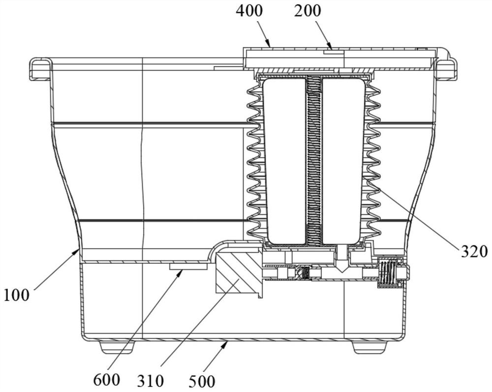
[0079] image 3 It is a schematic structural view of the foot bath in Example 2 of the present application, as Figure 1 to Figure 3 As shown, the main difference between the second embodiment and the first embodiment is that the lifting actuator 320 is different.
[0080] In this embodiment, the driving mechanism 310 includes an air pump, and the lifting actuator 320 includes an air bag. The airbag is connected to the foldable basin body 100 and the air pump, and the airbag is indirectly connected to the foldable basin body 100 through the upper cover 400 . The air pump is used to control the air volume in the airbag in response to the first lifting signal, so that the airbag performs lifting movement, and the folding basin is used to unfold or fold when the airbag performs lifting movement, wherein the first lifting signal corresponds to the inflation volume of the air pump Signal.
[0081] When the foot bath needs to be unfolded, the air pump inflates the air bag, and th...
Embodiment 3
[0085] Figure 4 It is a schematic flow chart of the footbath control method in Example 3 of the present application, Figure 5 It is the flow chart of the foot bath device control of the single lifting device in the third embodiment of the application, as Figure 4 and Figure 5 As shown, the footbath control method in this embodiment is used in a footbath, and the footbath includes the footbath mentioned in Embodiment 1 and Embodiment 2.
[0086] Such as Figure 1 to Figure 3 As shown, the foot bath includes a folding basin 100, a lifting device 300 and an electric control board 600, the lifting device 300 is connected to the folding basin 100, and the folding basin 100 is used for folding or unfolding when the lifting device 300 performs lifting movement, and the electric control The board 600 is used to implement the footbath control method.
[0087] Such as Figure 4 and Figure 5 As shown, the footbath control method includes:
[0088] S710: Send a first lifting s...
PUM
 Abstract
Description
Claims
Application Information
 - R&D Engineer
- R&D Manager
- IP Professional
- Industry Leading Data Capabilities
- Powerful AI technology
- Patent DNA Extraction
Browse by: Latest US Patents, China's latest patents, Technical Efficacy Thesaurus, Application Domain, Technology Topic, Popular Technical Reports.
© 2024 PatSnap. All rights reserved.Legal|Privacy policy|Modern Slavery Act Transparency Statement|Sitemap|About US| Contact US: help@patsnap.com