Light emitting diode driving circuit

A technology of light-emitting diodes and driving circuits, which is applied in the directions of instruments, static indicators, etc., can solve the problem that the driving circuit of light-emitting diodes cannot perform dynamic detection, and achieve the effect of avoiding the display effect.

Active Publication Date: 2022-04-12
AU OPTRONICS CORP
View PDF12 Cites 0 Cited by
  • Summary
  • Abstract
  • Description
  • Claims
  • Application Information

AI Technical Summary

Problems solved by technology

[0005] In view of the above-mentioned problems in the prior art, the object of the present invention is to provide a light-emitting diode driving circuit to solve the problem that the existing light-emitting diode driving circuit cannot perform dynamic detection

Method used


Image

  • Light emitting diode driving circuit
  • Light emitting diode driving circuit
  • Light emitting diode driving circuit

Examples


Embodiment Construction

[0085] In order to facilitate the understanding of the technical features, content and advantages of the present invention and the effects that can be achieved, the present invention is hereby combined with the accompanying drawings and described in detail in the form of embodiments as follows, and the figures used therein are only intended to For the purpose of illustrating and assisting the description, it may not be the true proportion and precise configuration of the present invention after implementation. Therefore, the proportion and configuration relationship of the attached drawings should not be interpreted or limited to the scope of rights of the present invention in actual implementation. Description.

[0086] In the drawings, the thickness or width of substrates, panels, regions, lines, etc., are exaggerated for clarity. Throughout the specification, the same reference numerals denote the same elements. It should be understood that when an element such as a substr...


PUM


Abstract

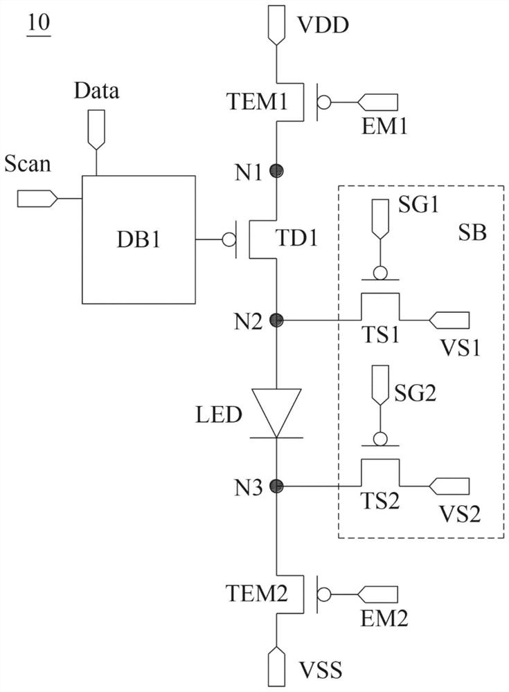
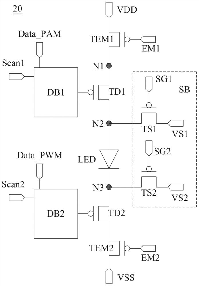
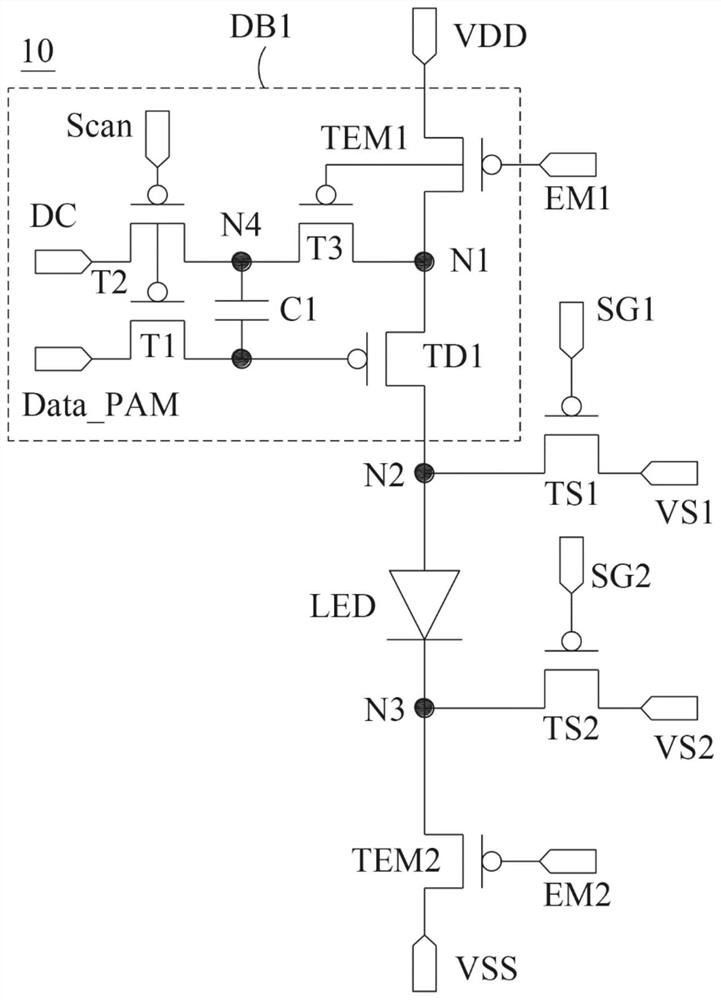
The invention discloses a light emitting diode driving circuit which comprises a first pulse wave circuit, a first light emitting control transistor, a light emitting diode, a sensing circuit and a second light emitting control transistor. The sensing circuit comprises a first sensing transistor and a second sensing transistor which are arranged at the two ends of the light-emitting diode, and the light-emitting state of the light-emitting diode can be dynamically detected through control of the sensing circuit, so that the light-emitting diode driving circuit is properly compensated, and the required display effect is achieved.

Description

technical field [0001] The present invention relates to a light emitting diode driving circuit, in particular to a light emitting diode driving circuit which is provided with a sensing circuit to dynamically detect the state of the light emitting diode during the light emitting interval of the light emitting diode. Background technique [0002] In light-emitting diode display panels, related drive circuits are designed to drive the light-emitting diodes in each pixel, but when the panel drive circuit encounters temperature changes, its forward voltage will also change accordingly. And operational efficiency will also be affected. When the above effects occur, the luminous effect of the light emitting diode will also be affected, thereby affecting the display effect of the entire display screen. [0003] For the influence caused by the temperature change, the display device of the light-emitting diode will perform corresponding compensation according to the change, so that t...

Claims


Application Information

Patent Timeline
Patent Type & Authority Applications(China)
IPC IPC(8): G09G3/00G09G3/32
Inventor 奚鹏博林振祺张毓清林凯俊陈致成
Owner AU OPTRONICS CORP
Why Eureka
Try Eureka