Partition post bilateral power supply traction network crossing power utilization system and control method

A traction network, zoning technology, applied in electrical components, power lines, circuit devices, etc., can solve problems such as reducing or eliminating the ineffective solution of bilateral power supply ride-through power, and achieves improved direct utilization, advanced technology, and regulation. handy effect

Active Publication Date: 2022-04-12
SOUTHWEST JIAOTONG UNIV
View PDF19 Cites 2 Cited by
  • Summary
  • Abstract
  • Description
  • Claims
  • Application Information

AI Technical Summary

Problems solved by technology

It can be seen that there is no effective solution to reduce or eliminate the ride-through power of bilateral power supply

Method used


Image

  • Partition post bilateral power supply traction network crossing power utilization system and control method
  • Partition post bilateral power supply traction network crossing power utilization system and control method
  • Partition post bilateral power supply traction network crossing power utilization system and control method

Examples


Embodiment 1

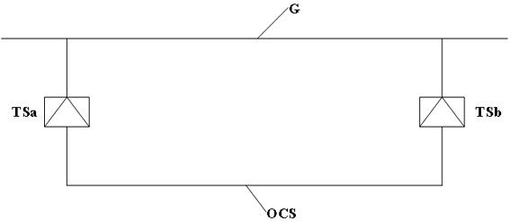
[0043] Such as figure 1 As shown, the single-line schematic diagram of the relationship between bilateral power supply and grid connection is shown in figure 1 As shown, the bilateral power supply traction network OCS forms a parallel structure with the grid G ​​through the traction substation TSa and the traction substation TSb on both sides. According to the parallel shunt principle, bilateral power supply will generate a current component parallel to the grid G ​​in the traction network OCS, called the balance current, and generate cross-current power, which will affect the electricity billing problem of the railway. If the power billing of the two substations with bilateral power supply adopts the method of return and reverse calculation, the problem can be solved well. If the return is not counted or the return is positively calculated, it will become an additional burden on the railway. to this end,

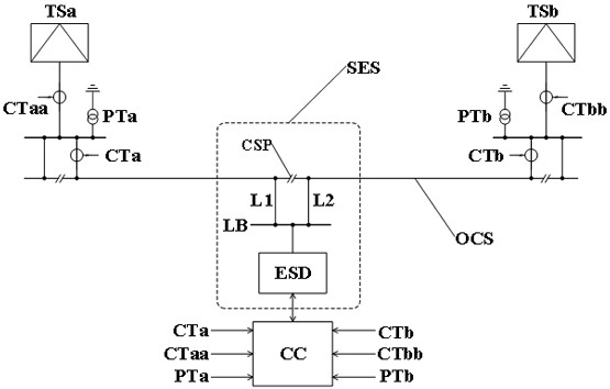
[0044] Such as figure 2 As shown, this embodiment provides a tract...

Embodiment 2

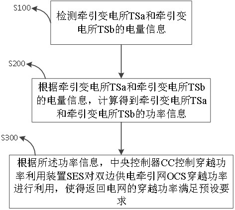
[0054] Such as image 3 As shown, this embodiment provides a control method based on the power utilization system of the traction network through the bilateral power supply provided by the sub-district station in Embodiment 1, which is applied to the central controller CC and realized through the following technical solutions: Step S100: Detect the traction variable Electricity information of power station TSa and traction substation TSb;

[0055] Step S200: According to the power information of the traction substation TSa and the traction substation TSb, calculate the power information of the traction substation TSa and the traction substation TSb, wherein the traction substation TSa or the traction substation TSb The power flowing to the traction network OCS is positive, and the power flowing from the traction network OCS to the traction substation TSa or traction substation TSb is negative;

[0056] Step S300: According to the power information, the central controller CC c...


PUM


Abstract

The invention provides a partition post bilateral power supply traction network crossing power utilization system and a control method, and relates to the field of traction power supply system circuit design. According to the traction network OCS, bilateral power supply is carried out by two adjacent traction substations TSa and TSb, a crossing power utilization device SES and a central controller CC are arranged in a partition station between the traction substations TSa and TSb, and the central controller CC obtains traction bus voltage and traction feeder current magnitude information of the traction substations TSa and TSb in real time. And controlling a crossing power utilization device SES to utilize the crossing power of the bilateral power supply traction network OCS, so that the crossing power returned to the power grid meets a preset requirement. Under the condition that a power supply structure of a power grid to a railway is not changed, the traction network ride-through power is utilized, negative effects caused by ride-through power metering are eliminated, and the advantages of bilateral power supply are brought into full play.

Description

technical field [0001] The invention relates to the field of circuit design of a traction power supply system, in particular to a traction network power utilization system and a control method for bilateral power supply in subregions. Background technique [0002] The electric separation phase of the electrified railway is the weak link in the whole traction power supply system. The neutral section of the electric separation phase forms a dead zone, causing power supply interruption. However, the power failure distance is more than 500 meters, which seriously restricts the good operation of the train, and even causes the train to stop on a slope when going uphill. The bilateral power supply of the electrified railway can cancel the electric phase split where the partition is located, eliminate the powerless area here, ensure the uninterrupted power supply of the train, and eliminate the hidden danger of excessive phase split. Bilateral power supply has the advantages of hig...

Claims


Application Information

Patent Timeline
Patent Type & Authority Applications(China)
IPC IPC(8): H02J3/06H02J3/28H02J13/00B60M3/06
Inventor 黄小红李群湛杨乃琪彭友任桃王翰林李昊阳
Owner SOUTHWEST JIAOTONG UNIV
Why Eureka
Try Eureka