A three-phase power supply ride-through power utilization system and control method

A three-phase, high-power technology, applied in the field of three-phase power supply through power utilization system and control, to achieve the effects of easy implementation, improved direct utilization, and advanced technology

Active Publication Date: 2022-05-24
SOUTHWEST JIAOTONG UNIV
View PDF18 Cites 0 Cited by
  • Summary
  • Abstract
  • Description
  • Claims
  • Application Information

AI Technical Summary

Problems solved by technology

[0006] The purpose of the present invention is to provide a three-phase power supply ride-through power utilization system, which can effectively solve the technical problem of utilizing the ride-through power existing between the main substation MS1 ​​and the main substation MS2

Method used


Image

  • A three-phase power supply ride-through power utilization system and control method
  • A three-phase power supply ride-through power utilization system and control method
  • A three-phase power supply ride-through power utilization system and control method

Examples


Embodiment 1

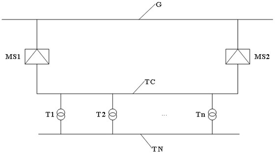
[0046] The single-line schematic diagram of the connection between the three-phase power supply and the grid is as follows figure 1 As shown, the three-phase bilateral cable TC forms a parallel structure with the grid G ​​through the main substations MS1 and MS2 on both sides. It can be known from the parallel shunt principle that a current component parallel to the grid G ​​will be generated on the three-phase bilateral cable TC, which is called the balance current, and the ride-through power will be generated, which will affect the electricity billing problem of the railway. If the electricity billing on the primary side of the two main substations with three-phase power supply adopts the method of back-counting, the problem can be solved very well. to this end,

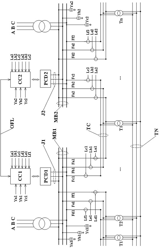
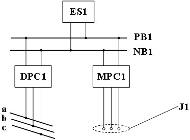
[0047] like figure 2 As shown, this embodiment provides a three-phase power supply ride-through power utilization system, including a power conversion device PCD1 and a controller CC1 arranged in the main substa...

Embodiment 2

[0061] like Figure 5 As shown, this embodiment provides a control method based on the traction grid bilateral power supply ride-through power utilization system provided in Embodiment 1, including:

[0062] Step S100: the controller CC1 and the controller CC2 obtain the real-time power information of the main substation MS1 ​​and the main substation MS2 respectively;

[0063] Step S200: the controller CC1 and the controller CC2 perform information exchange according to the real-time power information obtained by each;

[0064] Step S300: the controller CC1 controls the power conversion device PCD1 to use the ride-through power according to the information exchange result; or, the controller CC2 controls the power conversion device PCD2 to use the ride-through power according to the information exchange result, so that the ride-through power returned from the main substation MS1 ​​to the grid or The ride-through power returned to the grid from the main substation MS2 meets th...


PUM


Abstract

The invention provides a three-phase power supply ride-through power utilization system and a control method, and relates to the field of traction power supply system circuit design. Including the power conversion device PCD1 and controller CC1 installed in the main substation MS1, the power conversion device PCD2 and the controller CC2 installed in the main substation MS2, three The phase bilateral cable TC supplies power to the traction network TN; the controller CC1 is used to obtain the power information of the main substation MS1 ​​in real time, and the controller CC2 is used to obtain the power information of the main substation MS2 in real time; the controller CC1 and the controller CC2 pass The optical fiber performs information exchange with the OFL, and the controller CC1 controls the power conversion device PCD1 to use the ride-through power according to the information exchange result or the controller CC2 controls the power conversion device PCD2 to use the ride-through power according to the information exchange result, so that the ride-through power returned to the power grid meets the preset requirements.

Description

technical field [0001] The invention relates to the field of circuit design of a traction power supply system, in particular to a three-phase power supply ride-through power utilization system and a control method. Background technique [0002] Rail transit power supply system is divided into DC system and AC system. The direct current system is generally adopted in urban rail transit, mainly subway and light rail. The DC system has problems such as insurmountable stray current pollution and difficulty in regenerative braking energy recovery. The main line railway mainly adopts the power frequency single-phase AC system. The single-phase power-frequency AC system has obvious shortcomings: power quality problems mainly based on negative sequence, train speed and traction loss caused by electrical phase separation, and electrical transient problems between trains and networks caused by trains passing through electrical phase separation. [0003] Three-phase power supply can...

Claims


Application Information

Patent Timeline
Patent Type & Authority Patents(China)
IPC IPC(8): H02J3/06H02J3/28H02J13/00B60M3/06
CPCY02B90/20Y04S40/124
Inventor 李群湛黄小红郭锴李子晗解绍锋易东
Owner SOUTHWEST JIAOTONG UNIV
Why Eureka
Try Eureka