Apparatus and method for necking container ends

a beverage container and open end technology, applied in the field of accessory and method for necking the open end of the beverage container, can solve the problems of wear associated with the moving parts in the ram that requires maintenance and equipment downtime at regular intervals, disuniform thickness of the neck, and detrimental consequences, so as to reduce the maintenance associated with the necking operation, minimize wear, and enhance the reliability

Inactive Publication Date: 2000-08-01
CROWN CORK & SEAL TECH CORP
View PDF26 Cites 28 Cited by
  • Summary
  • Abstract
  • Description
  • Claims
  • Application Information

AI Technical Summary

Benefits of technology

It is a goal of the present invention to provide an apparatus and method for necking an open end of a beverage container that enhances the reliability and reduces the maintenance associated with the necking operation by minimizing wear, while diminishing the negative effects of center ring float. It is a further goal to improve the effectiveness of the necking operation.
The necking die (especially the first stage) may also have a slope surface disposed on a lower portion of the necking die for aligning the container as the container is pushed into the necking die. The punch sleeve and necking die form a substantially annular gap therebetween for receiving a sidewall on the container therein. Preferably, a punch body is removably coupled to the punch sleeve. The punch body has an outer diameter that is referenced to an inside surface of the necking die. Because the punch sleeve may be concentrically coupled to the punch body, the punch sleeve may be accurately and repeatably aligned with the die.
The punch body forms a longitudinal bore therethrough that forms a compressed air passage to channel compressed air from a main compressed air passage to a plenum disposed in the necking tool. The compressed air pressurizes the container during the necking operation to stiffen the sidewall during necking and to disengage the container from the center ring after necking. The punch sleeve extends past a narrow portion of the gap formed between the sleeve and necking die such that the container disengages from the die before it disengages from the sleeve. During this period, as well as during the actual necking, the compressed air is diverted through the gap formed between the sleeve and the die to keep the gap clean of debris, which may prevent defects in subsequent cans.
A method is also provided that includes the steps of positioning a container relative to a first necking die and a first punch sleeve; producing relative longitudinal movement of the container toward the first necking die to engage the external surface of a portion of the open end of the container with the first necking die at an angle to deform the sidewall radially inward; maintaining a fixed position of the first necking die relative to the first punch sleeve during the relative movement of the container toward the first necking die; and producing relative longitudinal movement of the container away from the first necking die to disengage the container from the first necking die. The method may include the step of pressurizing an interior chamber of the container. Further, the container may disengage from the die before disengaging from the sleeve, which encourages compressed air to flow through the gap formed between the sleeve and the die to keep the gap clean of debris.

Problems solved by technology

However, for both the constant motion and differential motion cams, the wear associated with the moving parts in the ram requires maintenance and equipment down-time at regular intervals.
Such a large degree of float, which increases with the wear of the ram and its sliding support, may allow the center ring to pinch the container against the die and may cause disuniform thickness of the neck.
Further, the motion of the center ring may cause it to contact the die and may transfer lubricant to the inside of the can, which has obvious detrimental consequences.

Method used


Image

  • Apparatus and method for necking container ends
  • Apparatus and method for necking container ends
  • Apparatus and method for necking container ends

Examples


Embodiment Construction

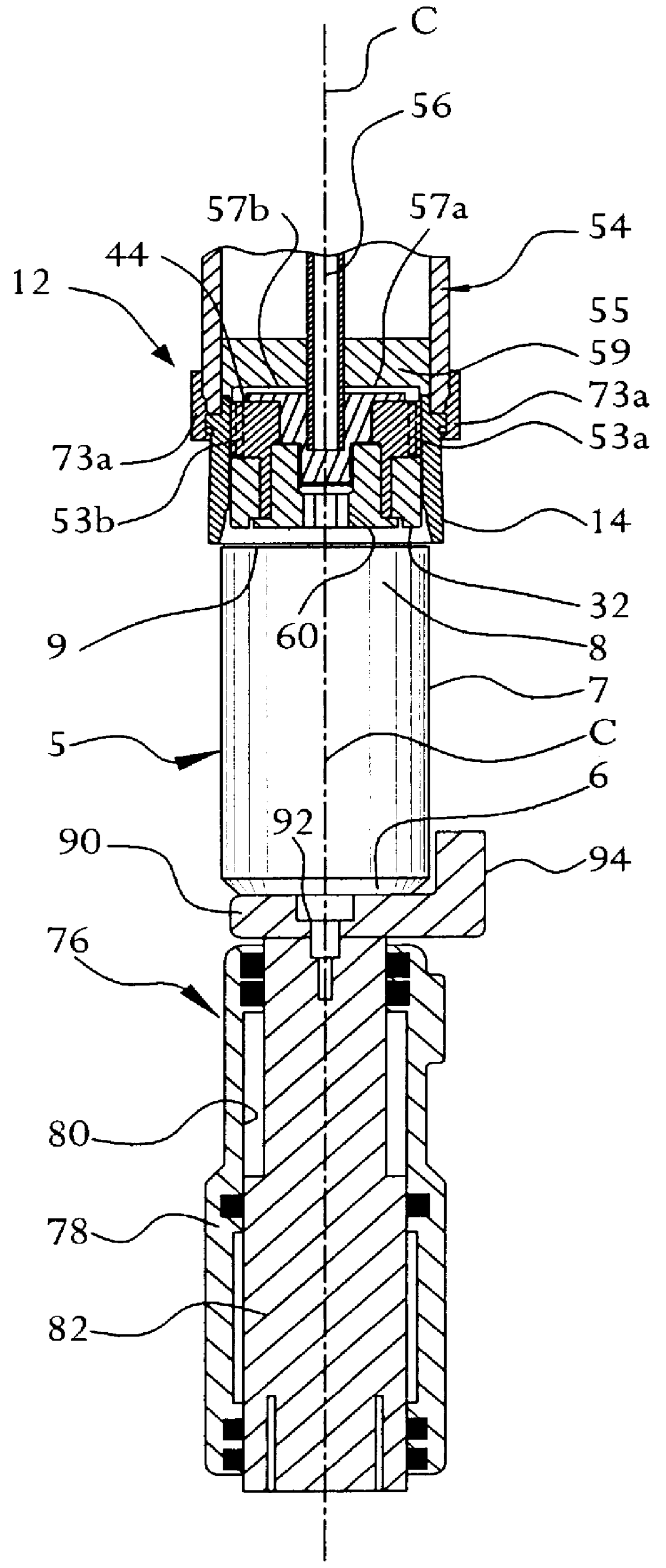
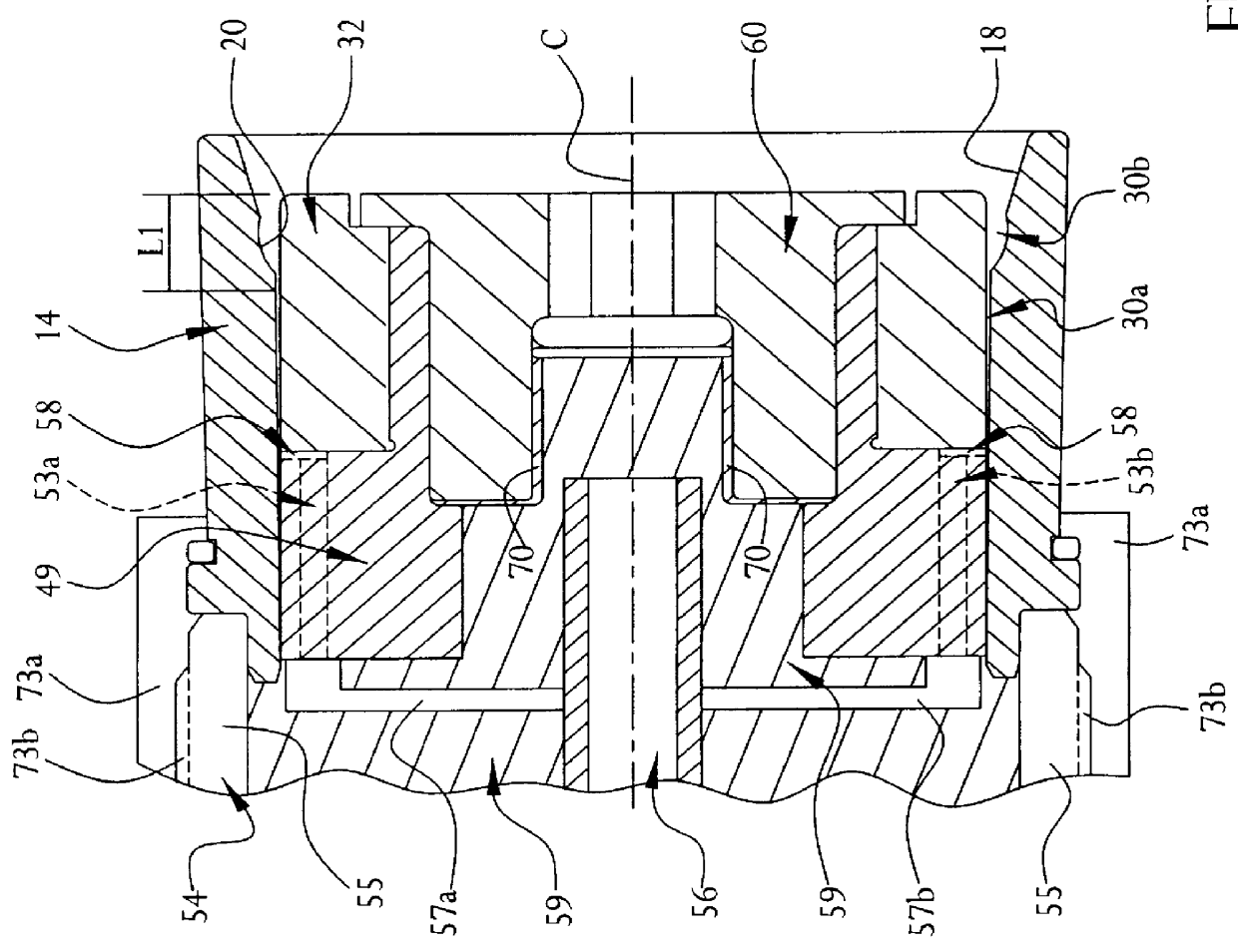
Referring to FIGS. 1 and 2, which show the assembled components to illustrate an embodiment of the present invention, a necking tool 10 includes a pusher subassembly 76 and an opposing upper forming or necking assembly 12. Necking assembly 12 includes a die 14, a punch sleeve 32, a punch body 44, an upper frame 54, and a retaining bolt 60. The components define a longitudinal centerline C. A can or container 5, which is the work piece for necking tool 10, is disposed between pusher assembly 76 and necking assembly 12. Container 5 includes a base 6, a sidewall 7, and a lip 9 formed at the end of an open end 8, which is opposite the base 6. Container 5 is in the stage of manufacturing before a lid is fixed thereto.

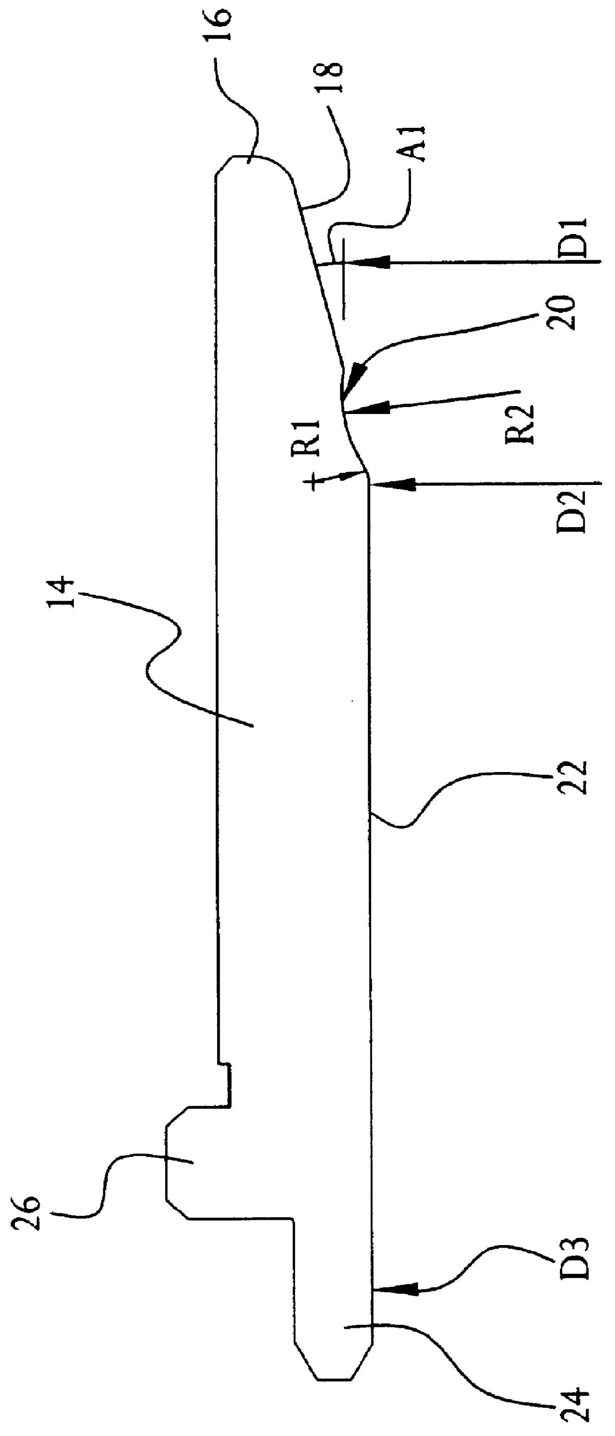
The discussion will provide dimensional information of the components, especially the dimensions and tolerances relating to the components that enable accurate positioning of punch sleeve 32 relative to die 14, to illustrate a particular embodiment of the present invention. ...


PUM

PropertyMeasurementUnit
angleaaaaaaaaaa
diameter D3aaaaaaaaaa
diameter D6aaaaaaaaaa

Abstract

A container necking tool, and corresponding method, for necking an aluminum beverage can is disclosed that includes a punch sleeve that is longitudinally fixed in relation to a necking die. The sleeve and die form a gap therebetween, into which a pusher assembly pushes the container to produce the neck on a necking contour surface. The necking tool also includes a punch body that has a longitudinal air passage therethrough. A plenum is formed between the punch body and sleeve to angularly distribute compressed air around the sleeve. Compressed air pressurizes the container during necking stage, and is diverted to the gap while the can is disengaged from the necking tool to keep the gap clean of debris.

Description

The present invention relates to machinery and methods for metal manufacturing, and more particularly to machinery and methods for manufacturing aluminum beverage containers, and even more particularly to necking an open end of aluminum beverage containers.The beverage container manufacturing industry has, for many years, sought to reduce the weight and amount of metal used in two piece beverage cans. A manifestation of this trend is cans having tapered necks. There are two basic techniques used to transform a roughly cylindrical drawn and ironed can body into a semi-finished container with a tapered neck: spin necking and die necking. Spin necking involves rotating the cylindrical container about its centerline axis and applying pressure to the open end to reduce its diameter. Die necking involves moving the open end of the can over a series of progressive dies that gradually reduce its diameter while providing a tapered smooth surface.A conventional die necking operation utilizes ...

Claims


Application Information

Patent Timeline
Patent Type & Authority Patents(United States)
IPC IPC(8): B21D51/26
CPCB21D51/2615
Inventor ASCHBERGER, ANTON A.
Owner CROWN CORK & SEAL TECH CORP
Why Eureka
Try Eureka