Method and apparatus for multi-source electrical energy grid-tied transformation

a technology of electrical energy grid and multi-source power, applied in photovoltaic energy generation, ac network circuit arrangement, sustainable manufacturing/processing, etc., can solve the problems of reducing the design complexity of inverters, consuming power on site, and reducing the capacity of each panel, so as to eliminate the negative impact of the bus and reduce the cost

Inactive Publication Date: 2011-01-27
YU WENJIANG
View PDF3 Cites 30 Cited by
  • Summary
  • Abstract
  • Description
  • Claims
  • Application Information

AI Technical Summary

Benefits of technology

[0012]The controller is designed with simplicity and robustness to minimize the cost and eliminate negative impact on the bus due to failure, other than the loss of the affected source / sources.

Problems solved by technology

Distributed generation has many traits including power security and improved distribution efficiency, meanwhile there arise new problems when they are tied to the existing electric power generation and application configuration that has been designed and operated with the implication that electric power are intensively generated in various locations.
By tying both sites to the grid, the site using power will consume the power generated at the other site where the power is not used at the moment.
The capacity of each panel is limited to a few hundreds of watts.
Efficiency problem arises in this type of setup when panels output unequally.
Similar problems exist when small wind tie together before a transformation stage converts their power output into power grid format; Prior arts also include small electric power inverters that transform the electric output from one solar panel or one small wind turbine into the grid format power and tie to grid.
To make this configuration economically viable, the inverter has to be down graded in design complexity and therefore reliability and quality suffer.

Method used


Image

  • Method and apparatus for multi-source electrical energy grid-tied transformation
  • Method and apparatus for multi-source electrical energy grid-tied transformation
  • Method and apparatus for multi-source electrical energy grid-tied transformation

Examples


Embodiment Construction

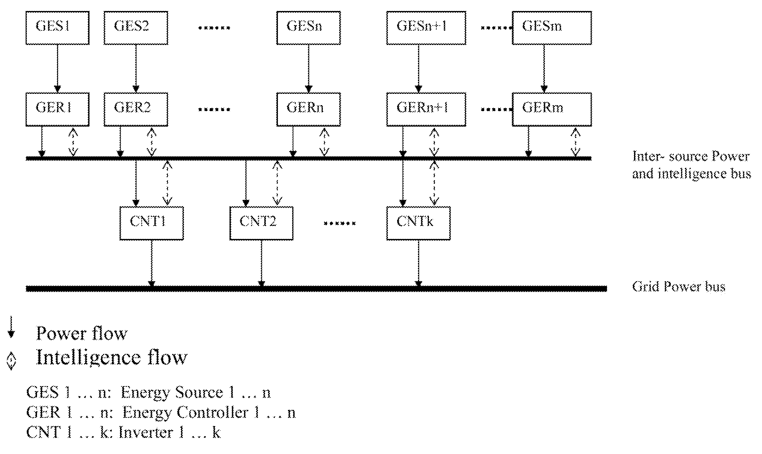
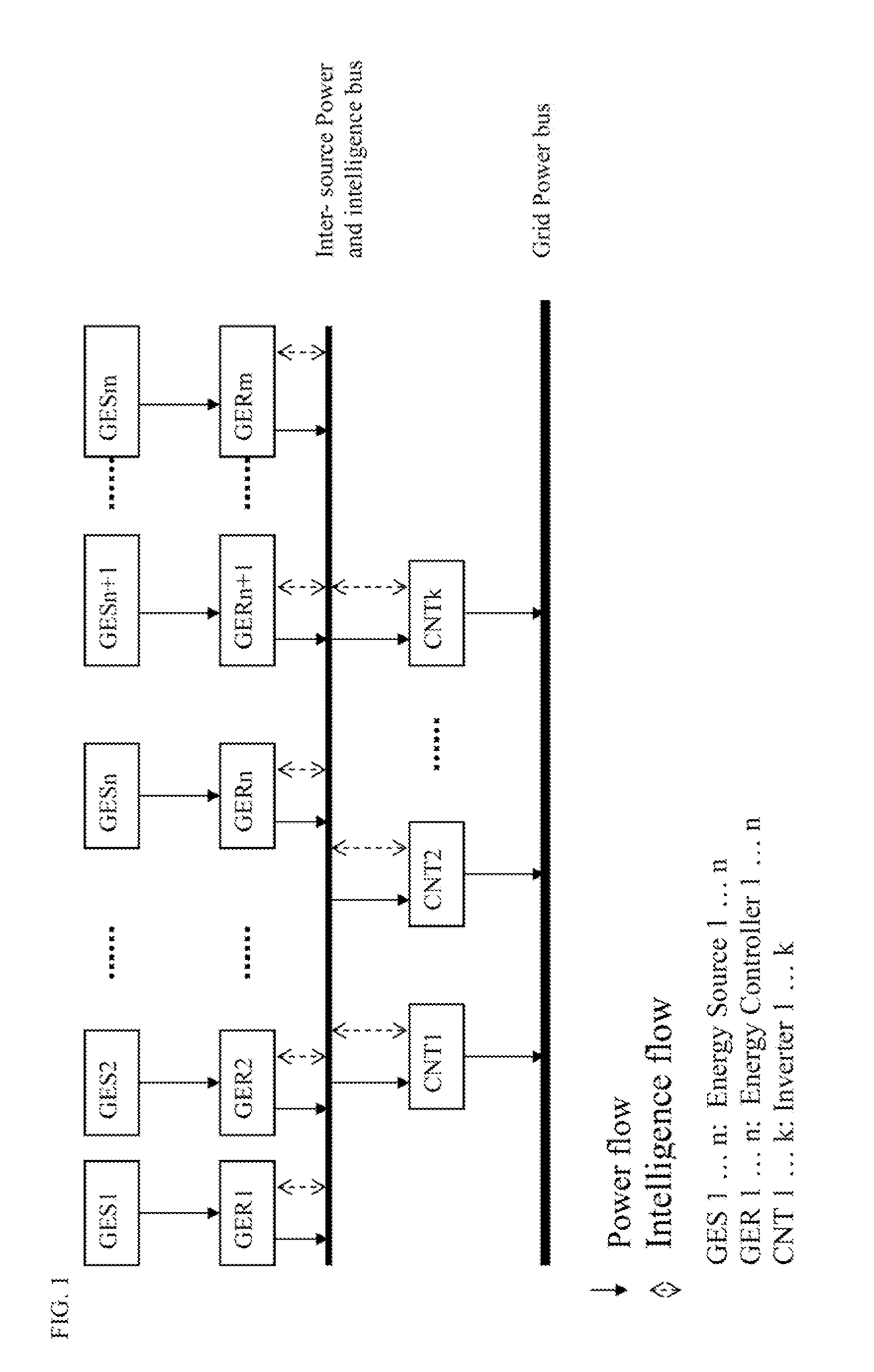
[0021]Top level configuration in this invention is illustrated in FIG. 1.

[0022]In this configuration, green energy sources can be solar panel, wind turbine or any other types of small scale (a few watts to a few thousands of watts in general) alternative electric power sources. The green energy controllers in this configuration refer to the devices that collaborate with other similar ones connected to the same inter-source power and intelligence bus to extract maximum available power from the corresponding power source at any given time, based on the intelligence flown on the bus. The controller is designed with simplicity and robustness to minimize the cost and eliminate negative impact on the bus due to failure, other than the loss of the affected source / sources. The inverters are devices responsible for maintaining the optimal status of the inter-source power bus, which is required for each controller to work to output maximum power from its connected source, by coordinating with...


PUM


Abstract

A method and apparatuses transform the electrical energy from multiple sources to grid compliant AC voltage. The apparatus according to one embodiment comprises: multiple energy sources (GES 1 to m in FIG. 1) from various power conversion devices; controllers (GER 1 to m in FIG. 1) pumping the maximum available electrical power to the DC inter-source bus; a hybrid inter-source DC bus carrying the electrical power from controllers to inverters and load level information among inverters; and inverters (CNT 1 to k) converting the DC power from the inter-source DC bus to grid compliant AC power.

Description

BACKGROUND OF THE INVENTION[0001]1. Field of Invention[0002]The present invention relates to electric power transformation systems, and more particularly to a method and apparatus for converting the electrical energy from multiple sources to grid compliant AC voltage.[0003]2. Description of Related Arts[0004]Growing green energy harvesting methods, such as small wind and solar electric power generation, create unique opportunities contributing to the long term global energy solution without jeopardizing environmental sustainability. Viable application methods of these green energy sources are based on distributed electric power generation.[0005]Distributed generation has many traits including power security and improved distribution efficiency, meanwhile there arise new problems when they are tied to the existing electric power generation and application configuration that has been designed and operated with the implication that electric power are intensively generated in various lo...

Claims


Application Information

Patent Timeline
Patent Type & Authority Applications(United States)
IPC IPC(8): H02J5/00
CPCH02J1/10Y02E10/563H02J5/00H02J3/383H02J2300/24H02J3/381Y02E10/56H02J2300/26H02J2300/28Y02P80/10
Inventor YU, WENJIANG
Owner YU WENJIANG
Why Eureka
Try Eureka