Patch equipment of joint motion sensor

A joint motion and sensor technology, applied in the field of sensors, can solve the problems of poor flipping form of double-sided patch equipment, and achieve the effect of fast efficiency and good coherence

Inactive Publication Date: 2022-04-15
ZHEJIANG UNIV
View PDF7 Cites 0 Cited by
  • Summary
  • Abstract
  • Description
  • Claims
  • Application Information

AI Technical Summary

Problems solved by technology

[0007] The purpose of the present invention is to solve the problem of the poor flipping form of the existing turntable sensor double-sided patching equipment, and propose a patching equipment for joint motion sensors

Method used


Image

  • Patch equipment of joint motion sensor
  • Patch equipment of joint motion sensor
  • Patch equipment of joint motion sensor

Examples


Embodiment Construction

[0025] The following are specific embodiments of the present invention and in conjunction with the accompanying drawings, the technical solutions of the present invention are further described, but the present invention is not limited to these embodiments.

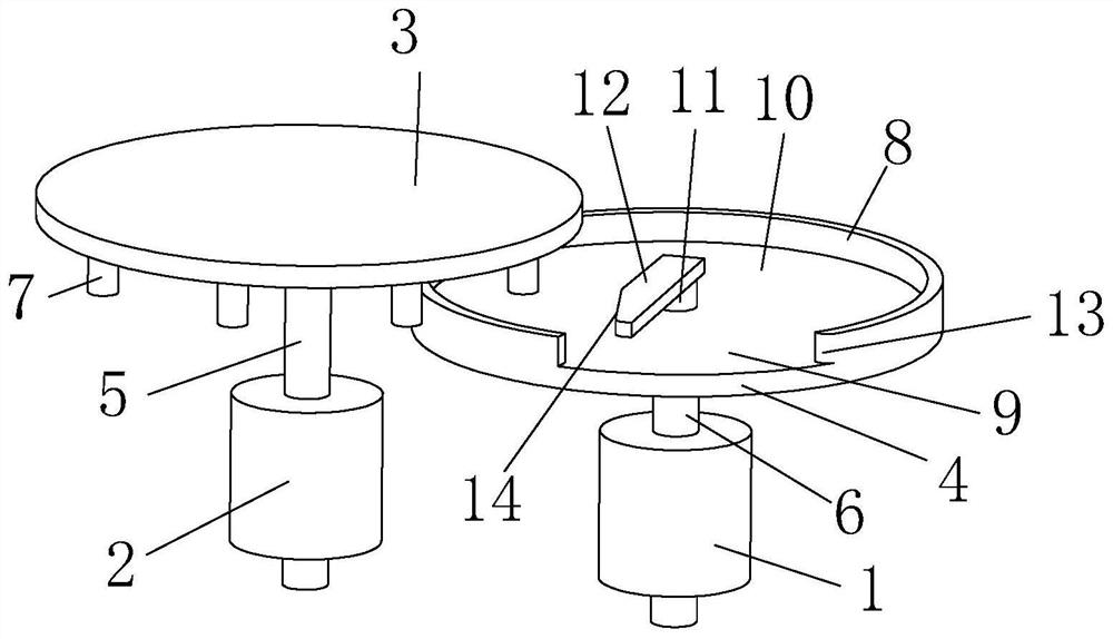
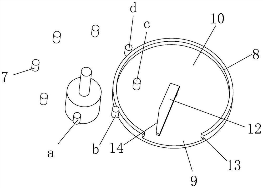
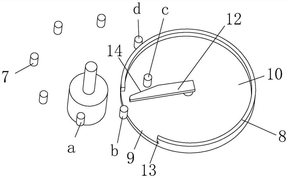
[0026] Such as Figure 8 As shown, the placement equipment of the joint motion sensor includes a station switching part for clamping the workpiece and intermittently transporting the workpiece in a circle, and a number of processing parts 17 for performing various processing operations on the workpiece (referring to the sensor). The processing parts 17 are evenly arranged around the circumference of the station switching part. The station switching part includes a switching bracket body 15 and a switching turntable 16 which is rotatably arranged on the switching bracket body 15. A plurality of clamps 18 are evenly arranged on the circumference of the switching turntable 16. The switching turntable 16 and the A periodic swi...


PUM


Abstract

The invention provides patch equipment of a joint motion sensor, and belongs to the technical field of sensors. The problem that an existing rotating disc type sensor double-face chip mounting device is poor in overturning mode is solved. The chip mounting equipment comprises a station switching component and a plurality of processing components, wherein the station switching component is used for clamping workpieces and transporting the workpieces circumferentially at intervals; the processing components are used for performing various processing operations on the workpieces; and the processing components are uniformly distributed around the circumference of the station switching component. Compared with the prior art, the chip mounting equipment does not need to occupy extra stations in the turn-over process, and the turntable can automatically complete intermittent station switching, so that the efficiency is high and the continuity is good.

Description

technical field [0001] The invention belongs to the technical field of sensors, and relates to a patch device for joint motion sensors. Background technique [0002] A sensor is a detection device that can sense the measured information and convert the sensed information into electrical signals or other required forms of information output according to certain rules to meet the requirements of information transmission, processing, storage, and display. , recording and control requirements. There are various types and application scenarios of the sensor. One of the application methods is to set it on the knee pads to monitor all aspects of the human body's joints during exercise. [0003] At present, in the assembly process of the joint motion sensor through equipment, in order to save the space occupied by the equipment and reduce the conveying procedure, most of them adopt the form of rotary table conveying. You can refer to the patent number CN201711402796.3, the patent n...

Claims


Application Information

Patent Timeline
IPC IPC(8): B05C13/02F16B11/00
Inventor 叶昭明王盛东王战
Owner ZHEJIANG UNIV
Why Eureka
Try Eureka