Method and arrangement in a floor structure drying process

Pending Publication Date: 2022-08-11
REDDO FLOOR SOLUTIONS AB
View PDF0 Cites 0 Cited by
  • Summary
  • Abstract
  • Description
  • Claims
  • Application Information

AI Technical Summary

Benefits of technology

[0003]An object of the invention is to obtain a quick an efficient drying process which will increase the temperature

Problems solved by technology

This prior art is, however, not optimally useful in sandwiched floor structures that are relatively poorly permeable to airflow.
The dehumidifier, on the one hand, will then not be effectively capable of drawing the moist air from the outlet opening without being overheated.
Trying to incre

Method used


Image

  • Method and arrangement in a floor structure drying process
  • Method and arrangement in a floor structure drying process
  • Method and arrangement in a floor structure drying process

Examples


Embodiment Construction

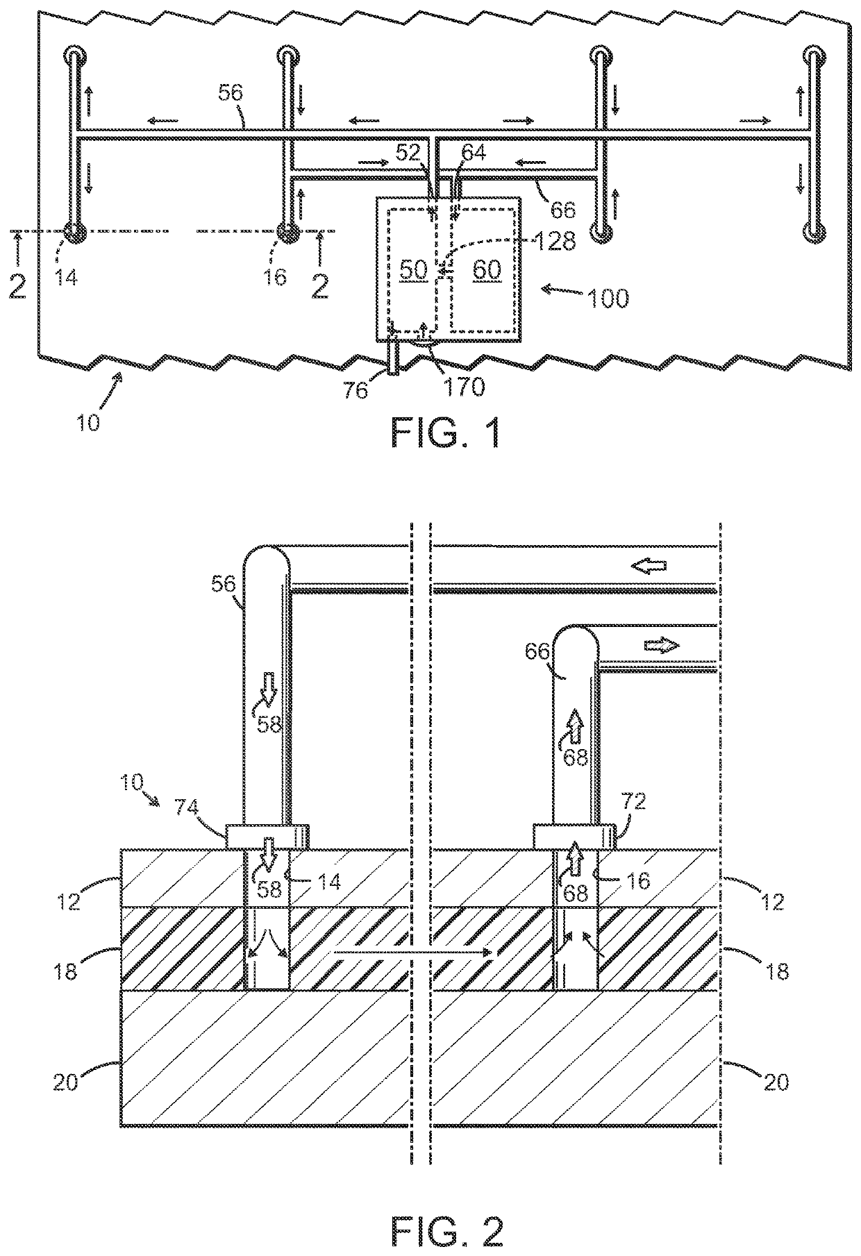
[0016]The sandwiched water damaged floor structure 10 shown in the example of FIGS. 1 and 2 includes a concrete subfloor 20, intermediate cellular plastics isolating layer 18 and a concrete top layer 12.

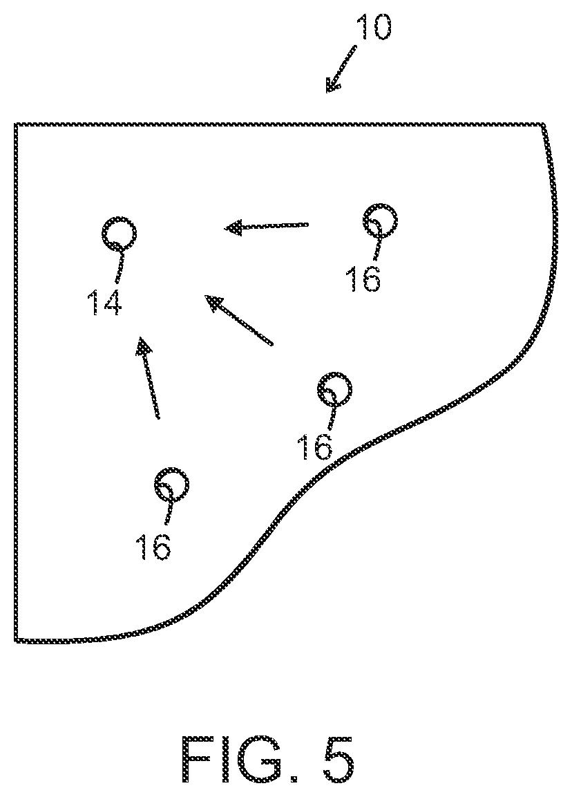
[0017]Before the drying operation takes place, a flooring (not shown) has been at least partially removed and a number of inlet and outlet openings 14 and 16, respectively, has been formed through the concrete top floor, for example by drilling / boring. While the openings 14, 16 not necessarily need to extend also through the isolating layer 18, this may be convenient and be the common case.

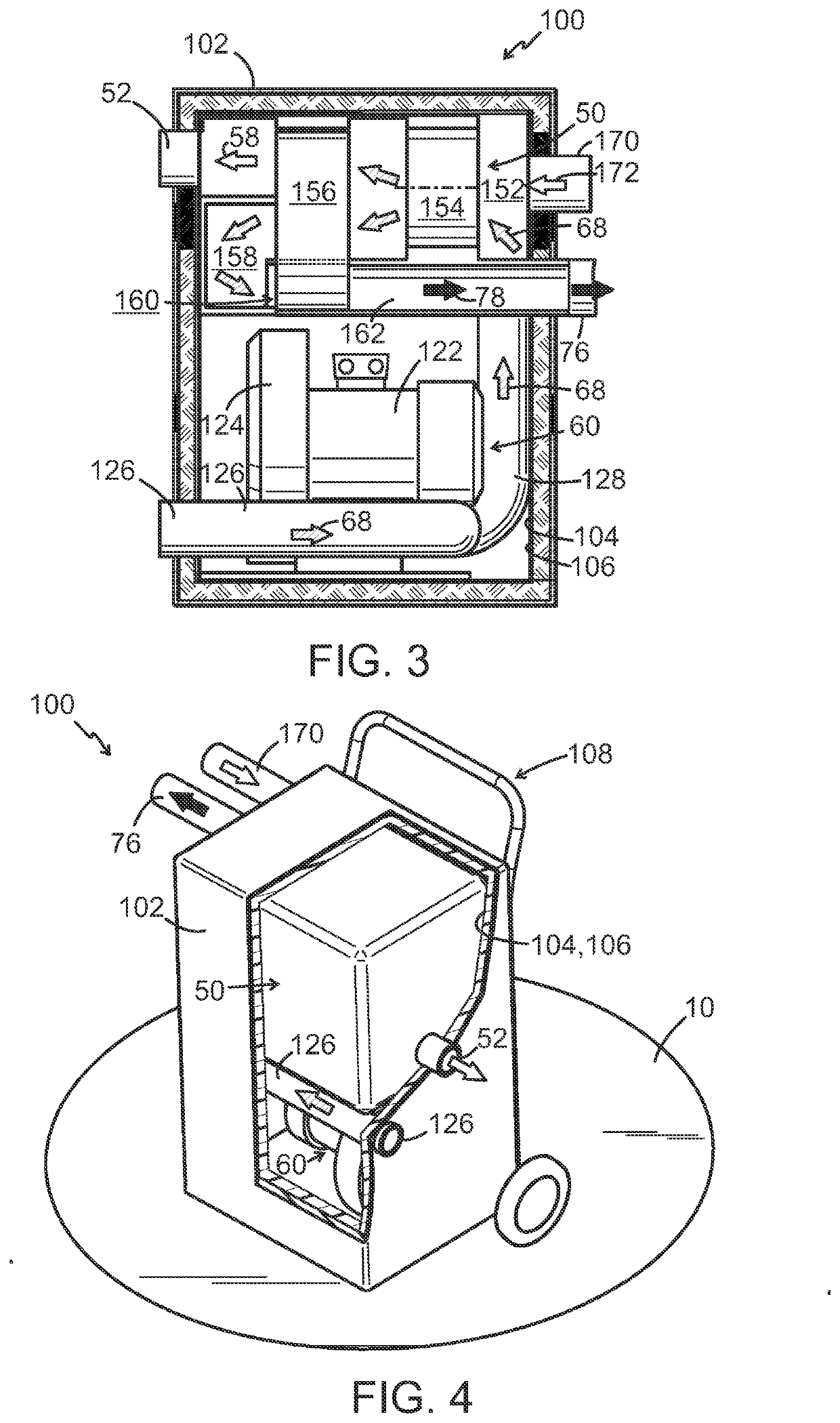
[0018]Inlet tubings 56 and outlet tubings 66 are then sealingly connected, for example via respective flanges 74 and 72, to the respective inlet and outlet openings 14 and 16. The inlet tubings 56 are connected to an outlet 52 of a dehumidifier 50 and the outlet tubings 66 are connected to an inlet 126 of a suction blower 60. Dehumidifier 50 and suction blower 60 are serially connected by a conduit...


PUM


Abstract

A method and arrangement for drying a water damaged sandwiched floor structure including a top concrete layer, an air permeable isolating layer and a concrete subfloor, comprising providing an air inlet opening and an air outlet opening through the concrete layer, and continuously in a closed loop flowing air through the isolating layer via the openings by a blower and a dehumidifier in serial connection. According to the invention the blower is a suction blower, whereby air is drawn from the outlet opening by the suction blower, and dry air is forced into the inlet opening by the dehumidifier.

Description

TECHNICAL AREA[0001]This invention relates to a method and an arrangement for drying a water damaged sandwiched floor structure including a concrete flooring, an air permeable isolating layer and a concrete subfloor, the method comprising providing an air inlet opening and an air outlet opening through the flooring, and continuously in a closed loop flowing dry air through the isolating layer via the openings by a blower and a dehumidifier in serial connection.BACKGROUND[0002]A prior art method and arrangement of a similar kind is disclosed in DE 3632424 A1. Therein, the blower is used to force dehumidified air into the inlet opening, whereas the dehumidifier draws moist air from the outlet opening. This prior art is, however, not optimally useful in sandwiched floor structures that are relatively poorly permeable to airflow. The dehumidifier, on the one hand, will then not be effectively capable of drawing the moist air from the outlet opening without being overheated. Trying to in...

Claims


Application Information

Patent Timeline
IPC IPC(8): E04B1/70E04G23/02F26B21/00F26B5/12
CPCE04B1/7092F26B5/12F26B21/001E04G23/0285E04G23/0288
Inventor ÅHSBERG, JOHAN
Owner REDDO FLOOR SOLUTIONS AB
Why Eureka
Try Eureka