Intelligent posture control system for lifting rotary lifting appliance

A technology of rotating spreader and attitude control, applied in the direction of load hanging components, transportation and packaging, can solve the problem of inability to eliminate the impact, and achieve the effects of simple and convenient maintenance, stable and reliable composition, and high detection accuracy.

Pending Publication Date: 2022-04-15
大连华锐智能化科技有限公司 +1
View PDF0 Cites 0 Cited by
  • Summary
  • Abstract
  • Description
  • Claims
  • Application Information

AI Technical Summary

Problems solved by technology

[0006] 3. The impact of braking cannot be eliminated

Method used


Image

  • Intelligent posture control system for lifting rotary lifting appliance
  • Intelligent posture control system for lifting rotary lifting appliance
  • Intelligent posture control system for lifting rotary lifting appliance

Examples


Embodiment 1

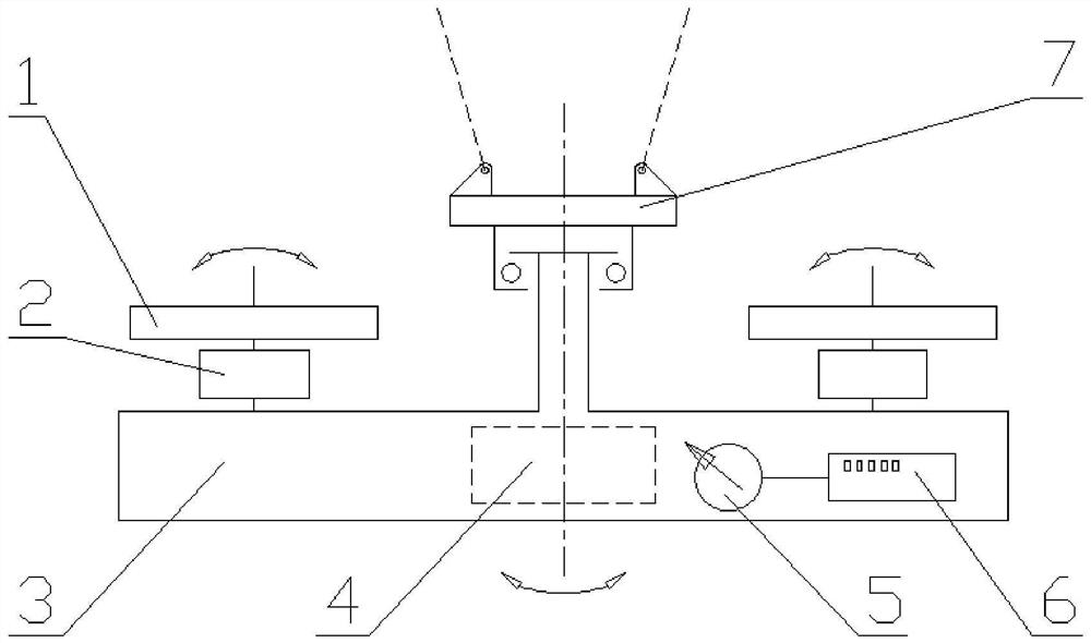
[0033] Such as figure 1 As shown, the present invention provides a smart gesture control system for a rehearsal rotating dish, including:

[0034] The kinetic energy unit provides kinetic energy to rotate the jack;

[0035] Hanging beam 3 for connecting the lifting point and the lift;

[0036] Power 4, preset to provide stable electrical energy for the system within the hanging beam;

[0037] Electronic compass 5, provided on the hanging beam for real-time monitoring angle data;

[0038] The solver and the controller 6 are connected to the electronic compass; the rotation angle data monitored by the electronic compass gives the movable portion specifically movement data;

[0039] The electronic compass 5 monitors the posture data of the hanging beam 3 in real time, and feeds back to the solver and the controller 6 to complete the closed loop control.

[0040] As an embodiment of the present application, the energy portion in the present embodiment is an inertial flywheel 1 and a d...

Embodiment 2

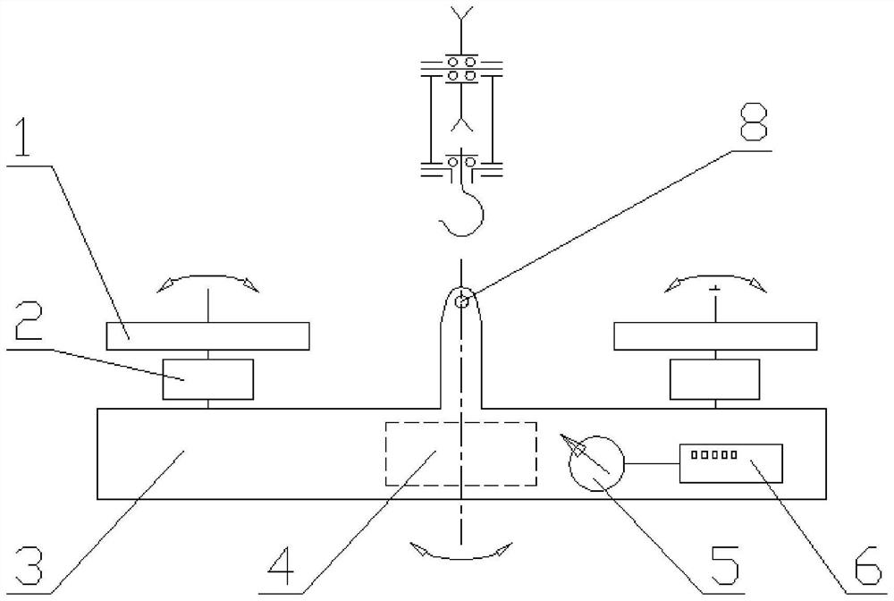
[0043] Such as figure 2 As shown, on the basis of the first example, the kinetic energy portion of the present embodiment includes: the inertial flywheel 1 and the drive motor 2 provided with the hanging beam integrated. In this case, the same portion as in the present embodiment is not described in this embodiment, and only the content distinguished from the first embodiment.

[0044]In this embodiment, the driving motor 2 is rotated by the inertial flywheel 1, and the hanging beam 3 is directly connected to the hook by the hook connection of the hanging point 8, and rotates through the thrust bearing in the hook, and realizes the multi-motor drive; electronic compass real-time monitoring The rotation angle of the hanging beam, the solver and the controller control the motion parameters of the drive motor based on the monitoring data of the electronic compass.

Embodiment 3

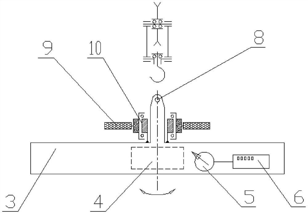
[0046] Difference to Embodiment One and Example II The present embodiment uses a single inertial flywheel drive. In this case, the same portion as in the present embodiment is not described in this embodiment, and only the content distinguished from the first embodiment.

[0047] Such as image 3 As shown, the kinetic energy unit includes: the rotor 10 of the flywheel 9 and the motor is fixed; the hanging beam 3 is directly connected to the hook through the hook connection of the hook, and the switch center of the motor is concentric with the swivel center of the electric machine. motor driven. The inner ring of the rotor of the motor is integral with the hanging beam 3.

[0048] The above-described embodiments of the present invention are merely description, and does not represent the advantages and disadvantages of the embodiment.


PUM


Abstract

The invention provides an intelligent posture control system for a lifting rotary lifting appliance, which comprises a kinetic energy part for providing kinetic energy to enable a jack to rotate; the suspended beam is used for connecting the hoisting point and a hoisted object; the power supply is preset in the suspended beam to provide stable electric energy for the system; the electronic compass is arranged on the suspended beam and is used for monitoring rotation angle data in real time; the resolver is connected with the controller and the electronic compass; specific motion data are provided for the kinetic energy part according to rotation angle data monitored by the electronic compass; and the electronic compass monitors attitude data of the suspended beam in real time and feeds back the attitude data to the solver and the controller to complete closed-loop control. The control system is stable and reliable in composition structure, simplifies a mechanical transmission part in a traditional lifting appliance, is simple and convenient to maintain, and facilitates long-term operation in an industrial place. The device is high in adaptability, high in detection precision, free of special requirements for the form of a lifting rope system, applicable to a common lifting hook set and beneficial to precise control over equipment.

Description

Technical field [0001] The present invention relates to the technical field of lifting transportation systems, and in particular, in particular, there is a smart gesture control system for a re-rotating dish. Background technique [0002] At present, the existing spreader has a horizontally rotating function, and the upper wire rope first produces a torque in reverse movement speed in the spreader, and the lower rotation portion can be stably rotated. Therefore, the wire rope system must be in the form of a horizontal torque. For the hook with thrust bearing, it is difficult to achieve controllable rotary movement in the horizontal surface of existing spreaders. The rotating portion of the spreader is mostly taken in the form of gear drive, that is, the drive mechanism and pinion constituting the transmission mechanism fixed to the non-rotation portion. The rotating section is mounted with a fixed large gear, pinion and a large gear to form a pair of drives, transfer power to the...

Claims


Application Information

Patent Timeline
Patent Type & Authority Applications(China)
IPC IPC(8): B66C13/16B66C13/18B66C13/06
Inventor 白永昕邱凯刘永刚张超
Owner 大连华锐智能化科技有限公司
Why Eureka
Try Eureka