Automobile tire quality analysis device and method based on edge cloud collaboration
A quality analysis device and technology of automobile tires, applied in the direction of automobile tire testing, measuring devices, inflation pressure measurement, etc., can solve the problems of inability to judge tire sidewall rubber, large error of detection results, and uniform distribution, so as to avoid tire deformation Abnormal, speed-up, and tire-mounting effects
- Summary
- Abstract
- Description
- Claims
- Application Information
AI Technical Summary
Problems solved by technology
Method used
Image
Examples
Embodiment 1
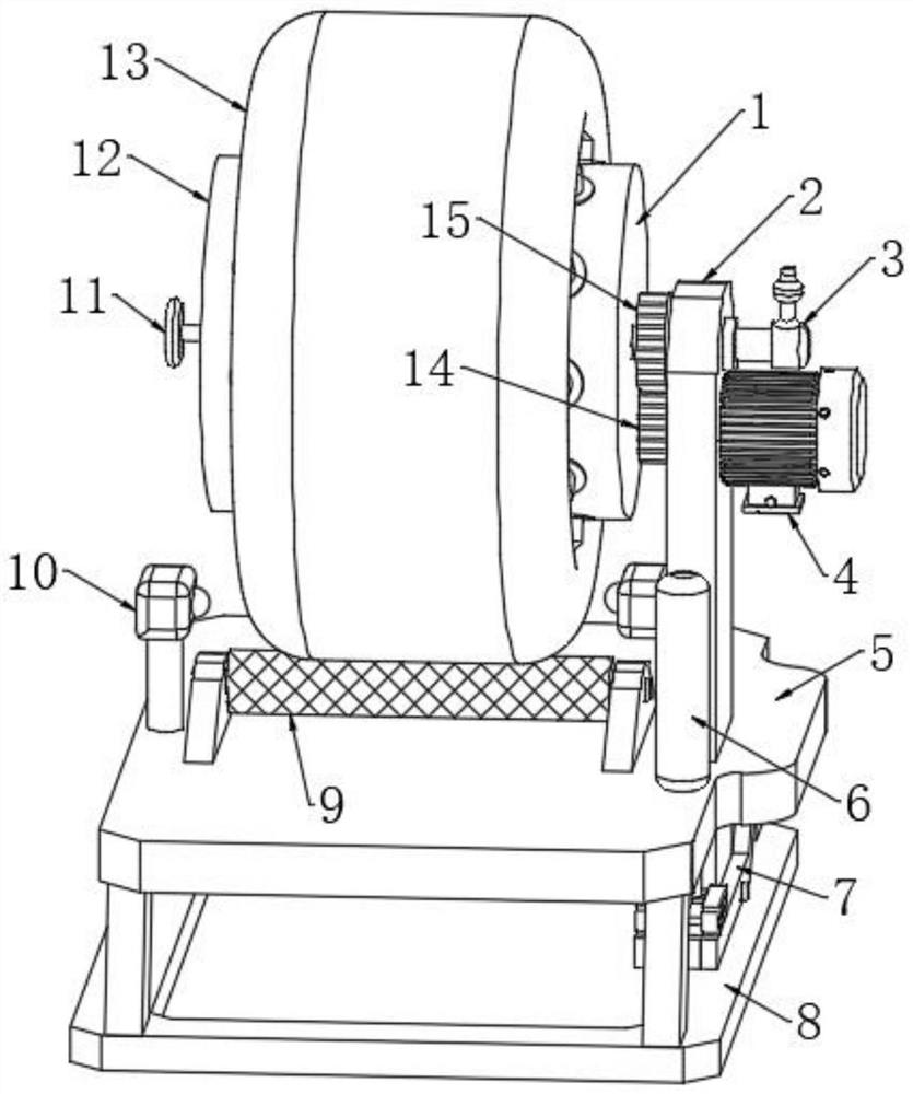
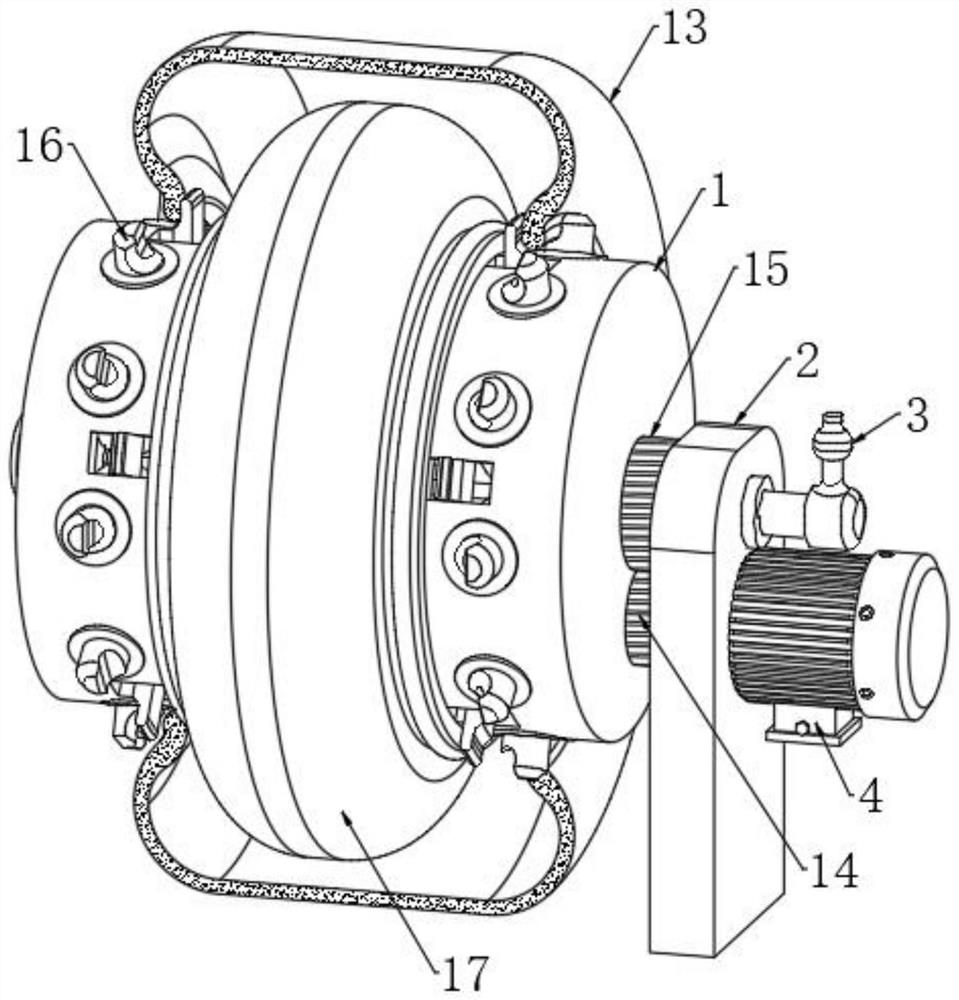
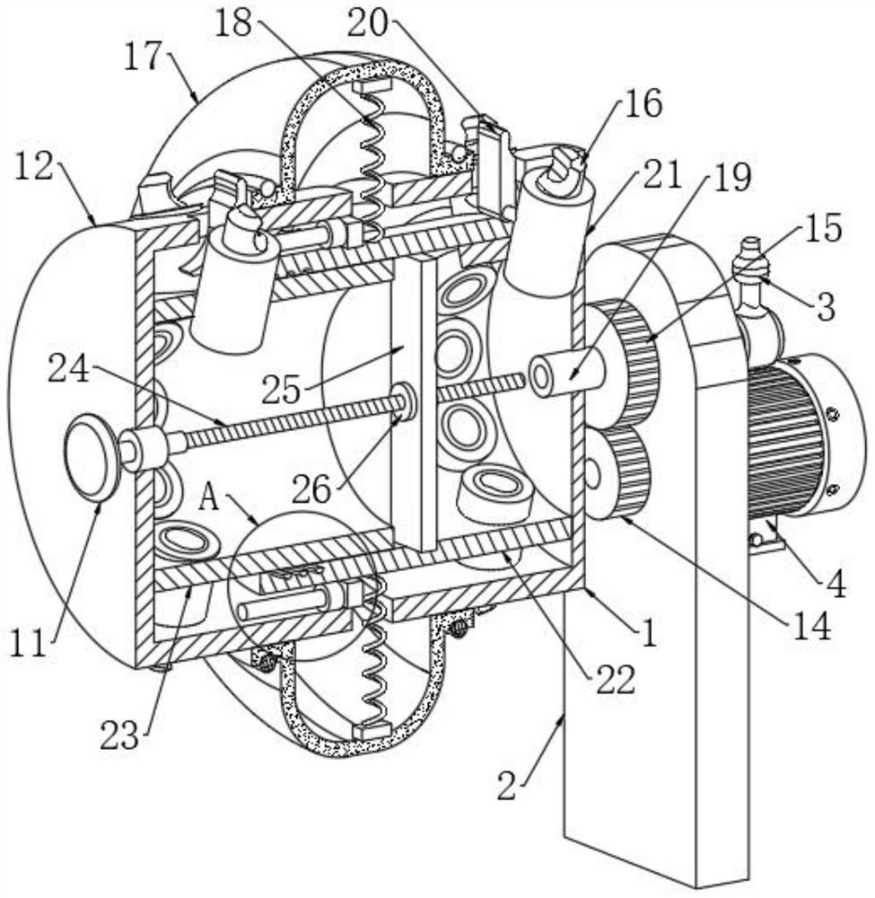
[0037] Refer to attached Figure 1-6 , an automobile tire quality analysis device based on edge-cloud collaboration, including a bracket 8, a horizontal plate 5, a support plate 2, a tire body 13 and two oscilloscope probes 10, the horizontal plate 5 is fixed on the upper end of the bracket 8, and the two oscilloscope probes 10 are arranged symmetrically On both sides of the tire body 13 and fixedly connected to the upper end of the cross plate 5, one side of the support plate 2 is rotatably connected with a cross pipe 19 through a rolling bearing, one end of the cross pipe 19 is fixedly connected with a rotary joint 3, and the other end of the cross pipe 19 is connected to There are multiple sets of fixing mechanisms, and the tire body 13 is socketed on multiple sets of fixing mechanisms. The fixing mechanism is used to fix the tire body 13, and inflate the tire body 13 after fixing, so that there is air pressure in the tire body 13 during detection. The upper end of the hori...
Embodiment 2
[0040] Embodiment 2: the difference based on Embodiment 1 is;
[0041] Refer to attached Figure 2-5 , the fixing mechanism includes two sleeves 21 arranged obliquely, the intersection point of the centerlines of the two sleeves 21 is located on the centerline of the horizontal tube 19, and one end of the sleeve 21 is sleeved with a push rod 28 through a round hole, and the push rod 28 One end of the push rod 28 is fixedly connected with a top block 16, and the side wall of the top block 16 is provided with a card groove that matches the bead of the tire body 13, and the other end of the push rod 28 is provided with a cylindrical groove, and a second cylindrical groove is fixedly connected in the cylindrical groove. Tension spring 31, one end of the second tension spring 31 extends to the outside of the cylindrical groove and is fixedly connected with the inner wall of the sleeve 21 by a fixed rod. The friction force between the accessories installed on its side wall and the ...
Embodiment 3
[0043] Embodiment 3: the difference based on embodiment 1 is;
[0044] Refer to attached Figure 6 , the transmission mechanism includes two support arms 7, the opposite sides of the two support arms 7 are rotationally connected with the two opposite sides of the support plate 2 through pin shafts, the lower end of the horizontal plate 5 is fixedly connected with a first frame body 37, the first The frame body 37 is provided with a support shaft, and the two ends of the support shaft are respectively connected to the side walls of the two support arms 7 through ball bearings. The end of the shaft runs through the side wall of the horizontal plate 5 and is fixedly connected with a horizontal shaft 35. Two second frame bodies 36 are sleeved on the shaft wall of the horizontal shaft 35, and the side walls of the two second frame bodies 36 are respectively connected with two supporting The side wall of the arm 7 is fixedly connected, the side wall of the support plate 2 is fixedl...
PUM
 Abstract
Description
Claims
Application Information
 - R&D
- Intellectual Property
- Life Sciences
- Materials
- Tech Scout
- Unparalleled Data Quality
- Higher Quality Content
- 60% Fewer Hallucinations
Browse by: Latest US Patents, China's latest patents, Technical Efficacy Thesaurus, Application Domain, Technology Topic, Popular Technical Reports.
© 2025 PatSnap. All rights reserved.Legal|Privacy policy|Modern Slavery Act Transparency Statement|Sitemap|About US| Contact US: help@patsnap.com


