Probe head protective sleeve of probe and use method of probe head protective sleeve

A technology for protective sleeves and needles, which is applied to the parts of electrical measuring instruments, measuring devices, instruments, etc., can solve the problems of easy damage of needles, and achieve the effect of improving protection rate and convenience

Pending Publication Date: 2022-04-15
康信达科技(苏州)有限公司
View PDF1 Cites 0 Cited by
  • Summary
  • Abstract
  • Description
  • Claims
  • Application Information

AI Technical Summary

Problems solved by technology

[0007] Therefore, the technical problem to be solved by the present invention is to overcome the problem in the prior art that the needle protective cover is assembled with the needle after the probe is produced, and the needle is easily damaged during the production process, and to provide a probe with a high protection rate. Needle guards for needles and methods of use thereof

Method used


Image

  • Probe head protective sleeve of probe and use method of probe head protective sleeve
  • Probe head protective sleeve of probe and use method of probe head protective sleeve
  • Probe head protective sleeve of probe and use method of probe head protective sleeve

Examples


Embodiment 1

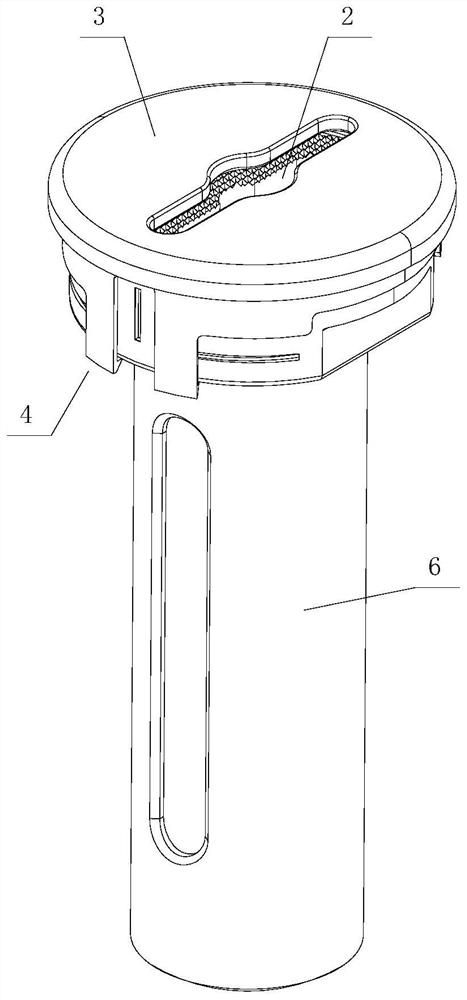
[0058] refer to Figure 5 As shown, a method for using the needle protection cover of a probe, for using the above-mentioned needle protection cover of the probe, comprises the following steps:

[0059] S11: Complete the assembly of the current needle head 2 and the current needle bar 1;

[0060] S12: covering the current needle 2 with the protective surface 3 to form protection for the current needle 2;

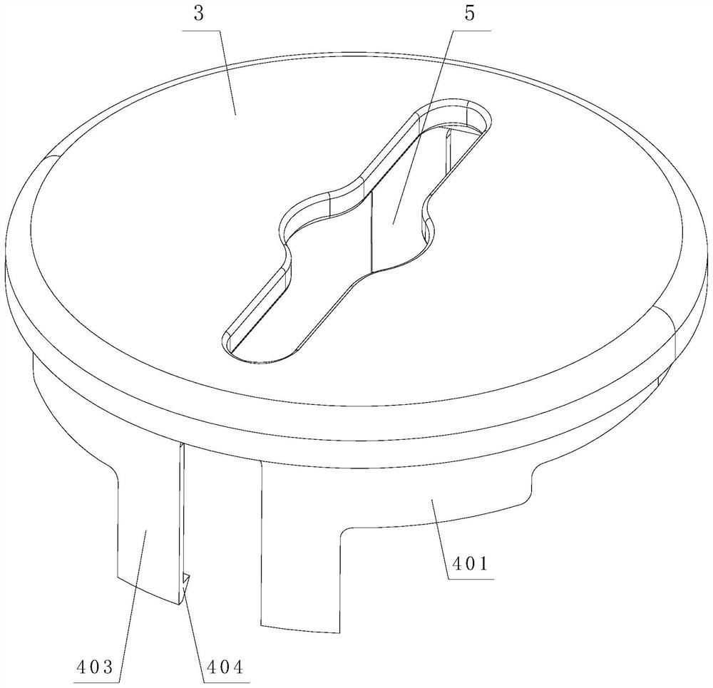
[0061] S13: Pass the voltage pin through the installation hole 5 on the protection surface 3.

[0062] After the current needle 2 and the current needle bar 1 are assembled, the current needle 2 is covered by the protective surface 3 to form protection for the current needle 2. At the same time, the installation of the subsequent voltage needle can be completed through the installation hole 5, so that the current needle 2 After the production and assembly are completed, it can be protected immediately, and the protection rate is improved.

Embodiment 2

[0064] refer to Image 6 As shown, a method for using the needle protection cover of a probe, for using the above-mentioned needle protection cover of the probe, comprises the following steps:

[0065] S21: Complete the assembly of the current needle head 2 and the current needle bar 1;

[0066] S22: Cover the current needle 2 with the protective surface 3 to form protection for the current needle 2;

[0067] S23: Pass the voltage pin through the installation hole 5 on the protection surface 3.

[0068] Among them, refer to figure 1 As shown, S22 includes:

[0069] S221: Cover the current needle 2 with the protection surface 3 to form protection for the current needle 2;

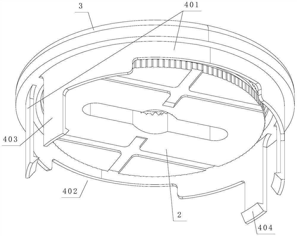
[0070] S222: Rotate the protective surface 3, so that the concave portion 402 of the first limiting member 4 is rotated to the platform surface.

[0071] Compared with Embodiment 1, in Embodiment 2, after the protection surface 3 is covered with the current needle 2, the protection surface 3 is rotated,...

Embodiment 3

[0073] refer to Figure 7 As shown, a method for using the needle protection cover of a probe, for using the above-mentioned needle protection cover of the probe, comprises the following steps:

[0074] S31: Complete the assembly of the current needle head 2 and the current needle bar 1;

[0075] S32: covering the current needle 2 with the protective surface 3 to form protection for the current needle 2;

[0076] S33: Pass the voltage pin through the installation hole 5 on the protection surface 3.

[0077] Among them, refer to figure 1 As shown, the S32 includes:

[0078] S321: covering the current needle 2 with the protective surface 3 to form protection for the current needle 2;

[0079] S322: Wrap the first extension part 403 around the receiving part of the current needle bar 1, and clamp the second extension part 404 on the bottom of the receiving part.

[0080] Compared with Embodiment 1, in Embodiment 3, after the protective surface 3 is covered with the current n...


PUM


Abstract

The invention relates to a probe head protective sleeve of a probe and a use method thereof, the probe head protective sleeve of the probe is clamped on a current probe rod and is used for protecting a current probe head, the top of the current probe rod is provided with a bearing part, and the current probe head to be protected is arranged in the bearing part. The current needle head to be protected is provided with an axial through hole for a voltage needle to penetrate through, and the current needle head to be protected comprises a protection surface which completely covers the current needle head and abuts against the current needle head; a first limiting piece is arranged at the bottom of the protection surface; and the protection surface is provided with a mounting hole matched with the axial through hole, so that the voltage pin can penetrate through the protection surface to enter the axial through hole. According to the probe head protection sleeve of the probe, the installation hole is formed in the protection surface, so that the voltage probe can penetrate through the protection surface to enter the axial through hole, it is guaranteed that the voltage probe can be normally assembled after the probe head protection sleeve is assembled on the probe head, and therefore the convenience in the installation process is improved.

Description

technical field [0001] The invention relates to the technical field of a needle protection cover, in particular to a needle protection cover of a probe and a use method thereof. Background technique [0002] After the probe is produced, it is usually necessary to protect the needle portion of the probe through a protective sleeve to avoid wear during transportation. [0003] However, the existing protective cover is usually assembled with the needle after the production of the probe is completed and before stacking and packing. However, during the production process, the needle still has a high possibility of being worn and scratched, resulting in the existing protective cover Reduced protection against needles. [0004] The patent with authorized notification number CN208953588U discloses a new type probe, which includes an end fixing base, a current needle bar, a current needle head and a voltage needle, and is characterized in that: a current needle bar is installed on t...

Claims


Application Information

Patent Timeline
Patent Type & Authority Applications(China)
IPC IPC(8): G01R1/067
Inventor 孙炳贵
Owner 康信达科技(苏州)有限公司
Why Eureka
Try Eureka