
Cooker glass panel assembly gluing tool

A technology for glass panels and stoves, which is applied in household stoves, household utensils, household stoves/stoves, etc., to achieve the effects of simple operation, reduced placement difficulty, and reduced labor intensity

Active Publication Date: 2019-12-03
NINGBO FOTILE KITCHEN WARE CO LTD
View PDF6 Cites 2 Cited by
  • Summary
  • Abstract
  • Description
  • Claims
  • Application Information

AI Technical Summary

Problems solved by technology

[0003] In the prior art, there is no tooling specially used for bonding the glass panel 1a, the decorative strip 4a, the connecting strip 2a, and the liquid receiving plate 3a at the same time. In order to improve work efficiency and replace purely manual operations, it is necessary to develop a set suitable for bonding Work

Method used


Image

  • Cooker glass panel assembly gluing tool
  • Cooker glass panel assembly gluing tool
  • Cooker glass panel assembly gluing tool

Examples


Embodiment Construction

[0024] The present invention will be further described in detail below in conjunction with the accompanying drawings and embodiments.

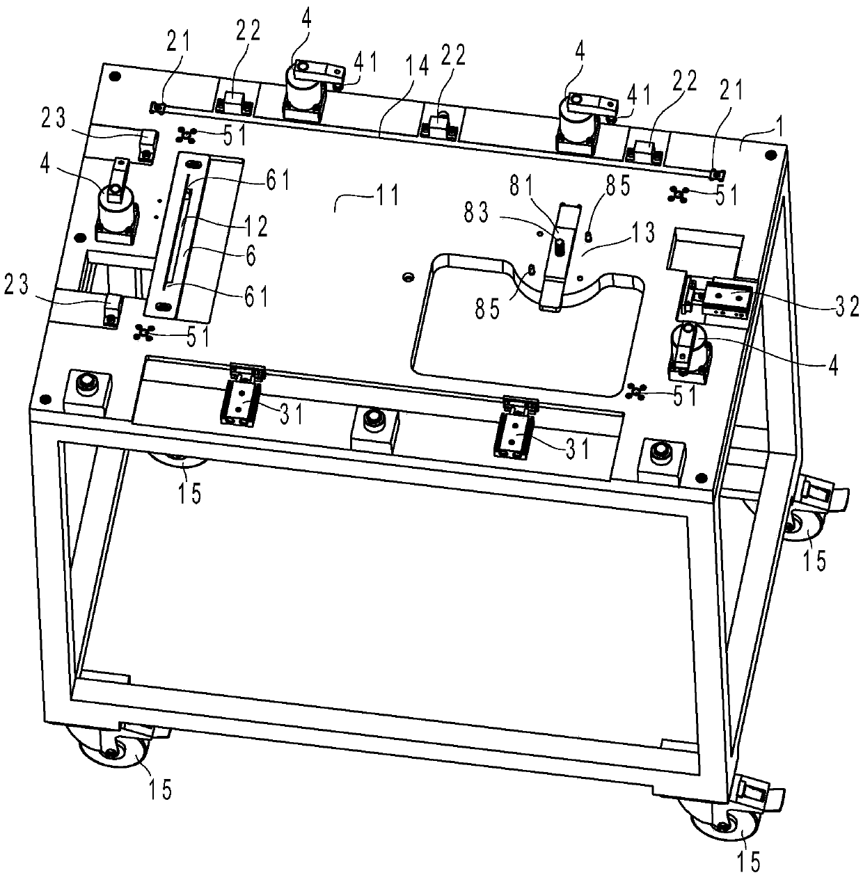
[0025] Such as image 3 As shown, the adhesive tooling for the glass panel assembly of the cooker in this embodiment includes a workbench 1 , a pressing cylinder 4 , a first translation cylinder 31 , a second translation cylinder 32 , a push cylinder 7 and an ejection cylinder 5 .

[0026] The workbench 1 has a working area 11, and the working area 11 has an installation hole 12 for connecting strips, a first installation area 14 for decorative strips, and a second installation area 13 for liquid trays. The first installation area 14 The opposite two sides are provided with the first positioning block 21 that can locate the decorative strip in the length direction, and the other side is provided with the second positioning block 22 that can position the decorative strip in the width direction; A positioning block 23, the third positioning blo...


PUM


Abstract

The utility model discloses a cooker glass panel assembly gluing tool. The tool comprises a workbench (1), a pressing air cylinder (4), a first translation air cylinder (31), a second translation aircylinder (32), a pushing air cylinder (7) and an ejection air cylinder (5). The workbench (1) is provided with a working area (11), and a mounting hole (12) for arranging a connecting strip, a first mounting area (14) for arranging a decorative strip and a second mounting area (13) for arranging a liquid bearing disc are formed in the working area (11). The first positioning blocks (21) capable ofpositioning the decorative strips in a length direction are arranged at the two opposite sides of the first installation area (14), and the second positioning blocks (22) capable of positioning the decorative strips in a width direction are arranged at the other side of the first installation area (14). Compared with the prior art, the cooker glass panel assembly gluing tool has the advantages ofbeing accurate in positioning, reliable in bonding, high in working efficiency and low in labor intensity.

Description

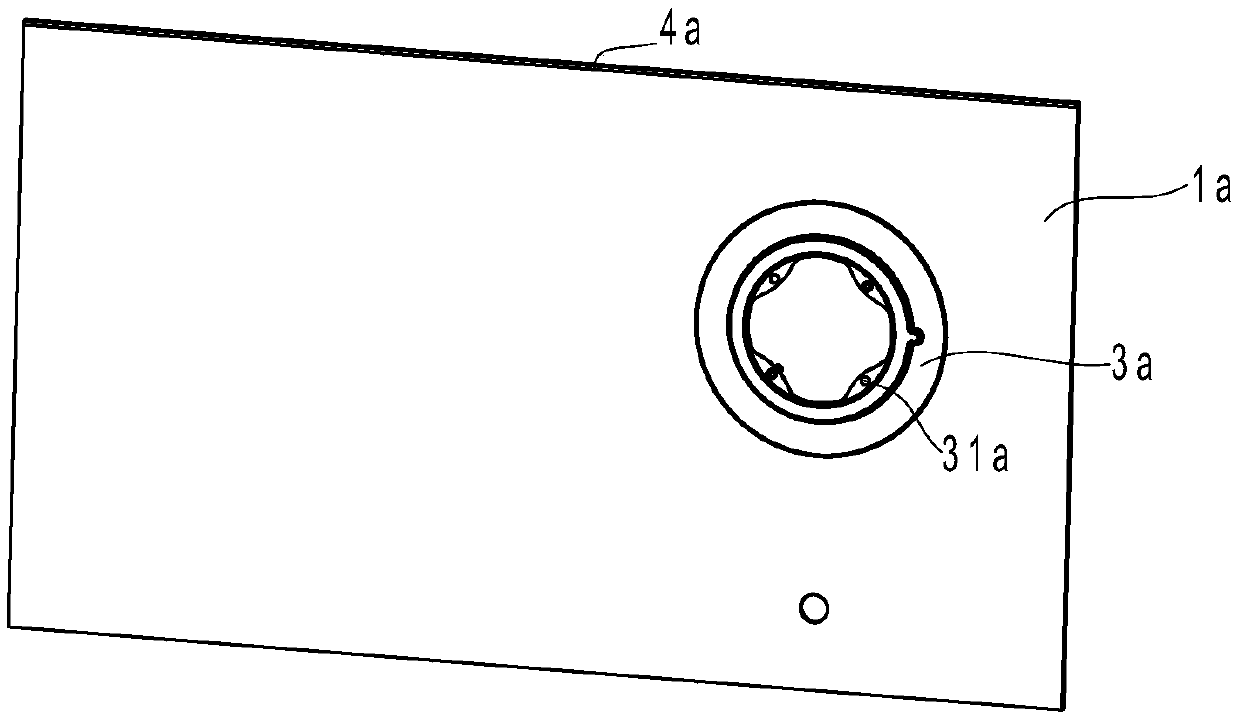
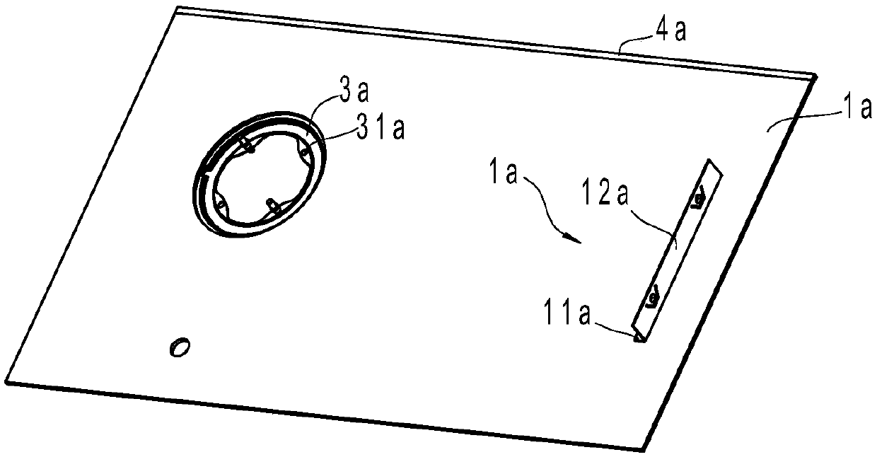
technical field [0001] The invention relates to a tool for assembling a glass panel assembly of a cooker, in particular to a tool capable of bonding a connecting strip, a decorative strip and a liquid receiving plate to a glass panel. Background technique [0002] In the prior art, gas-electric stoves appeared. One side of the gas-electric stove can be used as a gas stove, and the other side is an induction cooker, which can use electricity. The main body of the gas-electric stove is generally a glass panel assembly, such as figure 1 with figure 2 As shown, the glass panel assembly is mainly composed of a glass panel 1a, a connecting strip 2a, a decorative strip 4a and a liquid receiving tray 3a arranged on the glass panel 1a. The traditional connecting strip 2a and the glass panel 1a are connected by screws, and the screw connection requires fine adjustment for the gap, and the operation is cumbersome. This method has been replaced by bonding. The section of the connecti...

Claims


Application Information

Patent Timeline
IPC IPC(8): F24C15/06
CPCF24C15/06
Inventor 梁明剑
Owner NINGBO FOTILE KITCHEN WARE CO LTD
Learn More