
Dental panoramic view

A panoramic view and image technology, applied in the field of dental panoramic view, can solve the problems of low detail, the model cannot accurately and realistically visualize the patient's teeth, and the 3D dental mesh model is time-consuming.

Pending Publication Date: 2022-04-15
ALIGN TECH
View PDF2 Cites 2 Cited by
  • Summary
  • Abstract
  • Description
  • Claims
  • Application Information

AI Technical Summary

Problems solved by technology

However, generating 3D dental mesh models can be time-consuming and processor-intensive to generate, and can result in low-resolution, low-detail 3D models that do not accurately and realistically visualize the surfaces of a patient's teeth

Method used


Image

  • Dental panoramic view
  • Dental panoramic view
  • Dental panoramic view

Examples


Embodiment Construction

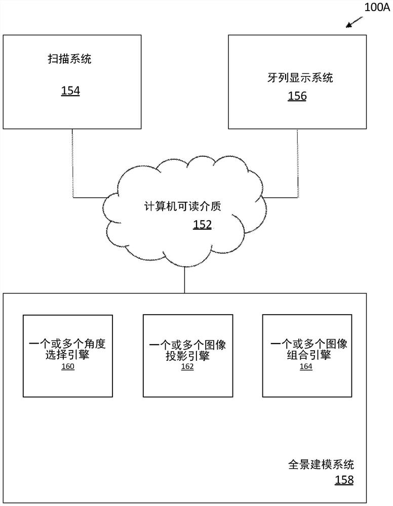
[0072] The present disclosure relates to systems, methods, computing device readable media, and devices for generating a model of an intraoral region (eg, one or more teeth, gums, jaw, etc.) of a subject. The systems, methods, and computing devices herein address technical problems related to the design and display of models of a patient's dental arch, including rapidly and efficiently displaying photorealistic images or models of a subject's dental surfaces.

[0073] Described herein is a scanning system or camera system for generating photo-realistic images of regions within a subject's oral cavity, including external or surface features of teeth, or internal features of teeth, And methods of using such scanning systems or camera systems are described herein. An intraoral scanner or camera system may include a wand that may be held by an operator (e.g., a dentist, dental hygienist, technician, etc.) and moved over one or more teeth of a subject to Scan the surface structure...


PUM


Abstract

Provided herein are apparatuses and methods for generating a panoramic rendering of a subject's teeth. Methods and processes for imaging teeth of a subject using a dental scan are provided. Methods and processes for automatic 3D rendering of teeth of a subject using scanned images are also provided. Methods and apparatus for generating simulated panoramic views of a subject's dentition from various perspectives are also provided.

Description

[0001] priority claim [0002] This patent application claims U.S. Provisional Patent Application No. 62 / 898,481, filed September 10, 2019, entitled "3D SCREEN VIEW FROM MULTIPLE PANORAMIC VIEWS," and filed in 2020 Priority to U.S. Provisional Patent Application No. 62 / 991,532, entitled "3D Screen Views from Multiple Panoramic Views," filed March 18, each of which is cited in The method is incorporated into this article as a whole. [0003] References [0004] All publications and patent applications mentioned in this specification are herein incorporated by reference in their entirety to the same extent as if each individual publication or patent application was specifically and individually indicated to be incorporated by reference. Background technique [0005] Many dental and orthodontic procedures can benefit from an accurate three-dimensional (3D) description of a patient's tooth shape and intraoral cavity. Surface representations of tooth 3D surfaces have proven to b...

Claims


Application Information

Patent Timeline
Patent Type & Authority Applications(China)
IPC IPC(8): A61C13/00A61C19/04A61B6/51
CPCA61C13/0004A61C19/04A61C9/0053A61C9/004G06T3/4038G16H50/50G16H30/40A61B6/463A61B6/465A61B6/5211A61N5/103A61B6/51
Inventor 玛雅·摩西沙伊·阿亚尔J·科斯洛夫斯基A·莱文A·祖尔蒂S·法卡什
Owner ALIGN TECH
Learn More