Automatic cutter for printer

An automatic cutter and printer technology, applied in metal processing, etc., can solve problems such as poor reliability, poor paper cutting, complex cutter reversing mechanism, etc., achieve long life and improve the quality of paper cutting

Pending Publication Date: 2022-04-19
XIAMEN RONGTA TECH
View PDF0 Cites 0 Cited by
  • Summary
  • Abstract
  • Description
  • Claims
  • Application Information

AI Technical Summary

Problems solved by technology

[0003] 1. At present, the meshing between the circular cutter and the fixed knife is insufficient, resulting in poor paper cutting. Otherwise, the accuracy of the parts needs to be improved to ensure the meshing between the circular cutter and the fixed knife, but the processing cost increases and the consistency is difficult to guarantee;
[0004] 2. The cutter reversing mechanism is complicated, and there are many parts, which increases the cost of parts and assembly, and the structure is complicated and the reliability is poor.

Method used


Image

  • Automatic cutter for printer
  • Automatic cutter for printer
  • Automatic cutter for printer

Examples


Embodiment 1

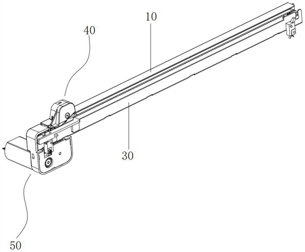
[0039] see Figures 1 to 12 , is an automatic cutter for a printer as Embodiment 1 of the present invention, comprising a horizontal fixed knife 10 and a circular cutter 20 slidingly connected with the fixed knife 10, the fixed knife 10 is inclined downward and vertically The angle formed by the direction is less than 90 degrees, and the front end of the circular cutter 20 along the paper cutting direction is attached to the cutting edge of the fixed knife 10, and its rear forms an included angle with the cutting edge of the fixed knife 10, and the included angle is an acute angle. ; Wherein, the angle formed by the fixed knife 10 and the vertical direction is α, and α is 87-89 degrees; the acute angle range is 1-3 degrees; a certain angle is formed between the circular cutter 20 and the fixed knife 10, Allowing the circular cutter 20 to mesh with the fixed knife 10 can more fully improve the quality of paper cutting and have a longer life.

[0040] The automatic cutter also ...

Embodiment 2

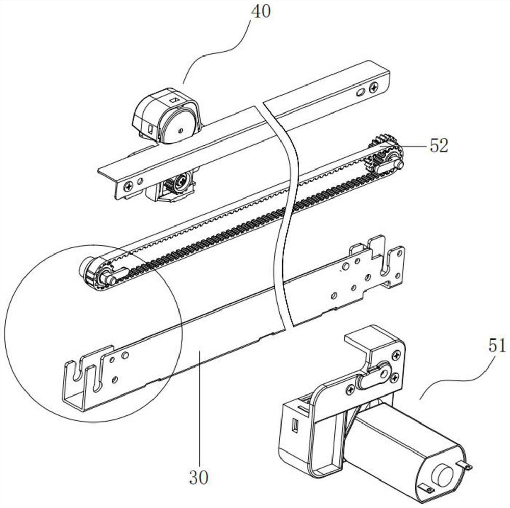
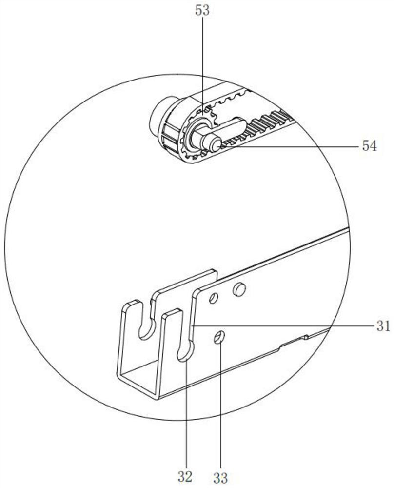
[0046] see Figure 13 , 14 , is an automatic cutter for a printer as Embodiment 2 of the present invention. The difference between this embodiment and the embodiment is that the plan adopted for the repeated movement of the bracket 41 is different; The connected bracket 41, the pressing block 46 for fixedly connecting the bracket 41 with the transmission belt 52, and the shaft detection switch 47 for sensing the position of the bracket 41 are arranged at both ends of the transmission belt 52, wherein the shaft detection switch 47 is fixedly arranged on the support On the seat 30, and on both sides of the bracket 41, there are extensions 412 for shaft detection and sensing; the motor drives the bracket 41 to slide, and when it is detected that the bracket 41 reaches one end of the conveyor belt 52, the motor reverses and drives the bracket 41 to the other end of the conveyor belt 52 Move, when the shaft detection switch at the other end detects that the bracket 41 is in place,...


PUM


Abstract

The invention provides an automatic cutter for a printer, which comprises a horizontally placed fixed cutter and a circular cutter in sliding connection with the fixed cutter, the fixed cutter inclines downwards and forms an angle less than 90 degrees with the vertical direction, and the front end of the circular cutter along the paper cutting direction is attached to the cutting edge of the fixed cutter. An included angle is formed between the rear part of the cutter blade and the cutting edge of the fixed cutter and is an acute angle; according to the automatic cutter, a certain included angle is formed between the circular cutter body and the fixed cutter body, the circular cutter body and the fixed cutter body are meshed more sufficiently, the paper cutting quality can be improved, parts are reduced, assembling is easy and convenient, the requirements for part machining and manufacturing precision are lower, and the service life is longer.

Description

technical field [0001] The invention relates to the technical field of printers, in particular to an automatic cutter for printers. Background technique [0002] The printer is a device that prints the calculation results or intermediate results of the computer on paper in accordance with the specified format in numbers, letters, symbols and graphics that can be recognized by humans. The existing A4 thermal printer paper does not have an automatic cutter. After the printer prints out the paper, it needs to be torn off manually. Manual tearing is not only inefficient, but also the torn paper is prone to problems such as unevenness. Although some structures can realize automatic paper cutting at present, there are the following problems: [0003] 1. At present, the meshing between the circular cutter and the fixed knife is insufficient, resulting in poor paper cutting. Otherwise, the accuracy of the parts needs to be improved to ensure the meshing between the circular cutter ...

Claims


Application Information

Patent Timeline
Patent Type & Authority Applications(China)
IPC IPC(8): B26D1/18B26D7/06B26D7/20B26D7/26B26D7/32
CPCB26D1/18B26D7/0625B26D7/2628B26D7/20B26D7/32B26D2007/322
Inventor 许开明许开河郑小华
Owner XIAMEN RONGTA TECH
Why Eureka
Try Eureka