Detector for injection mold

An injection mold and detector technology, applied in the field of injection mold detectors, can solve the problems of bubbles around the product, insufficient product injection, increase injection time, etc., and achieve the effects of avoiding bubbles, keeping neatness, and avoiding clogging

Pending Publication Date: 2022-04-19
彭扬
View PDF8 Cites 0 Cited by
  • Summary
  • Abstract
  • Description
  • Claims
  • Application Information

AI Technical Summary

Problems solved by technology

[0002] Injection molding is a method of producing industrial products. Products usually use rubber injection molding and plastic injection molding. Injection molding machine is the main molding equipment that uses plastic molding molds to make thermoplastic or thermosetting materials into plastic products of various shapes. Injection molding is It is realized by injection molding machine and mold. The disadvantages of injection molding include insufficient injection of the product and bubbles around the product. The methods to overcome the above problems include heating the molding cavity, increasing the injection time, and enhancing exhaust. However, these adjustment methods Usually it needs to be adjusted through repeated experiments, and the appropriate parameters have been reached to make the product reach the qualified state. The main problem to be solved by the present invention is how to detect the plastic filling state inside the molding cavity of the mold, provide direct data for debugging, and improve the debugging of injection molds. efficiency

Method used


Image

  • Detector for injection mold
  • Detector for injection mold
  • Detector for injection mold

Examples


Embodiment Construction

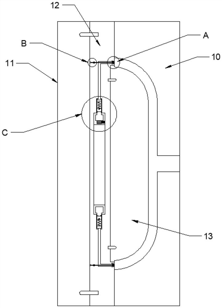
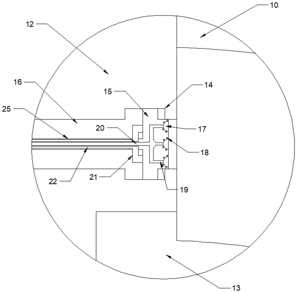
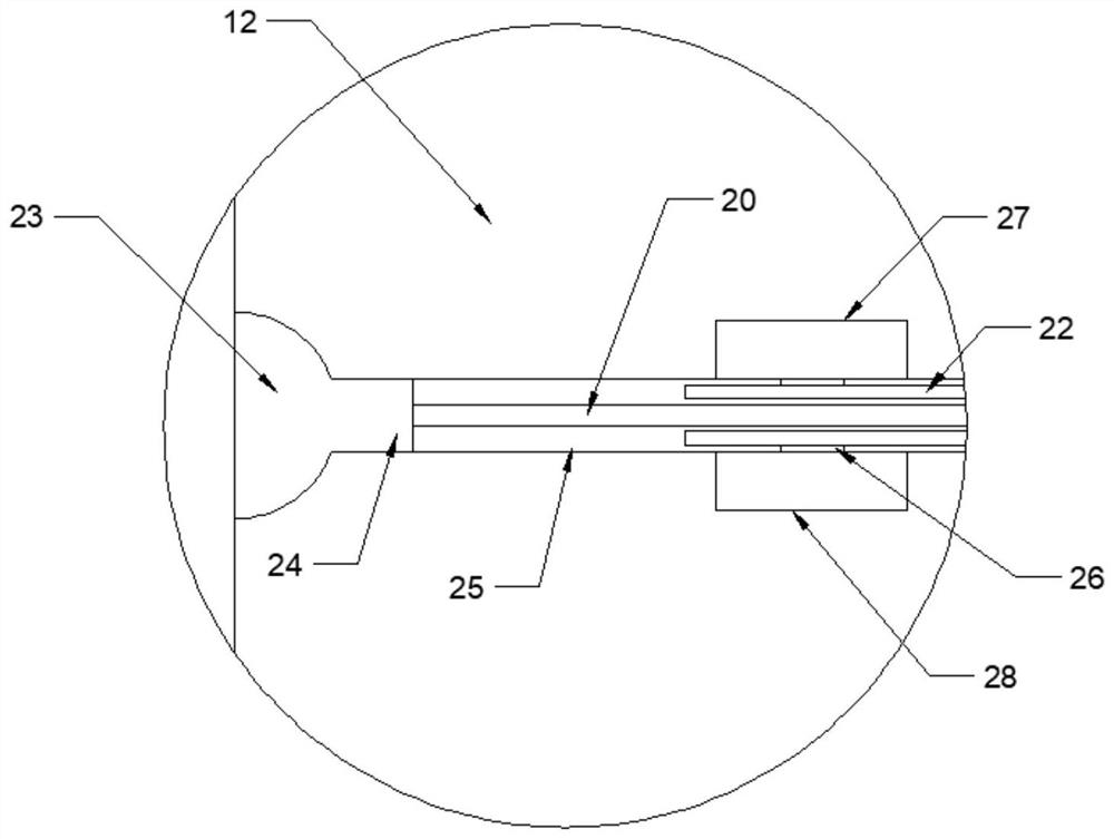
[0021] Combine below Figure 1-4 The present invention is described in detail, wherein, for the convenience of description, the orientations mentioned below are defined as follows: figure 1 The up, down, left, right, front and back directions of the projection relationship itself are the same.

[0022] A kind of detector for injection mold described in conjunction with accompanying drawing 1-4, comprises die 10, punch 13, and described punch 13 side is provided with detection body 12, and described detection body 12 side is provided with fixed body 11. The fixed body 11 is connected to the injection molding machine, a molding cavity is formed between the concave mold 10 and the male mold 13, and a detection hole 14 is provided on the side of the detection body 12 close to the molding cavity. The detection hole 14 Distributed around the molding cavity, one side of the detection hole 14 opens toward the die 10, and a detection slider 15 is slid in the detection hole 14, and the...


PUM


Abstract

The invention relates to the related technical field of injection molding, and discloses a detector for an injection mold, the detector comprises a female mold and a male mold, one side of the male mold is provided with a detection body, one side of the detection body is provided with a fixing body, the fixing body is connected with an injection molding machine, and a molding cavity is formed between the female mold and the male mold. Detection holes are formed in the side, close to the forming cavity, of the detection body, the detection holes are distributed around the forming cavity, by arranging the detection holes, a detection sliding block, an exhaust groove, an exhaust pipe, a temperature control groove and the like, fluid in the forming cavity is increased, and when the fluid at a certain position pushes the detection sliding block to slide for a certain distance in the detection hole, the detection sliding block is pushed to slide for a certain distance; the distance sensor senses the moving distance of the detection sliding block, and when the detection sliding block moves, it is considered that gas is completely exhausted at the position, and the position is filled with liquid.

Description

technical field [0001] The invention relates to the technical field related to injection molding, in particular to a detector for injection molds. Background technique [0002] Injection molding is a method of producing industrial products. Products usually use rubber injection molding and plastic injection molding. Injection molding machine is the main molding equipment that uses plastic molding molds to make thermoplastic or thermosetting materials into plastic products of various shapes. Injection molding is It is realized by injection molding machine and mold. The disadvantages of injection molding include insufficient injection of the product and bubbles around the product. The methods to overcome the above problems include heating the molding cavity, increasing the injection time, and enhancing exhaust. However, these adjustment methods Usually it needs to be adjusted through repeated experiments, and the appropriate parameters have been reached to make the product rea...

Claims


Application Information

Patent Timeline
Patent Type & Authority Applications(China)
IPC IPC(8): B29C45/76
CPCB29C45/76
Inventor 彭扬
Owner 彭扬
Why Eureka
Try Eureka