
Temperature control early warning device for high and low voltage equipment

An early warning device, high and low voltage technology, applied in the construction parts of electrical equipment, electrical equipment shells/cabinets/drawers, modification with gaseous coolants, etc., to avoid self-opening and reduce workload

Inactive Publication Date: 2022-04-19
JIANGXI HJATIS POWER IND CO LTD
View PDF1 Cites 3 Cited by
  • Summary
  • Abstract
  • Description
  • Claims
  • Application Information

AI Technical Summary

Problems solved by technology

[0005] Aiming at the deficiencies of the prior art, the present invention provides a temperature control early warning device for high and low voltage equipment that does not require manual real-time monitoring, so as to overcome the shortcomings of the existing devices that require manual real-time monitoring

Method used


Image

  • Temperature control early warning device for high and low voltage equipment
  • Temperature control early warning device for high and low voltage equipment
  • Temperature control early warning device for high and low voltage equipment

Examples


Embodiment 1

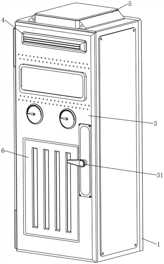
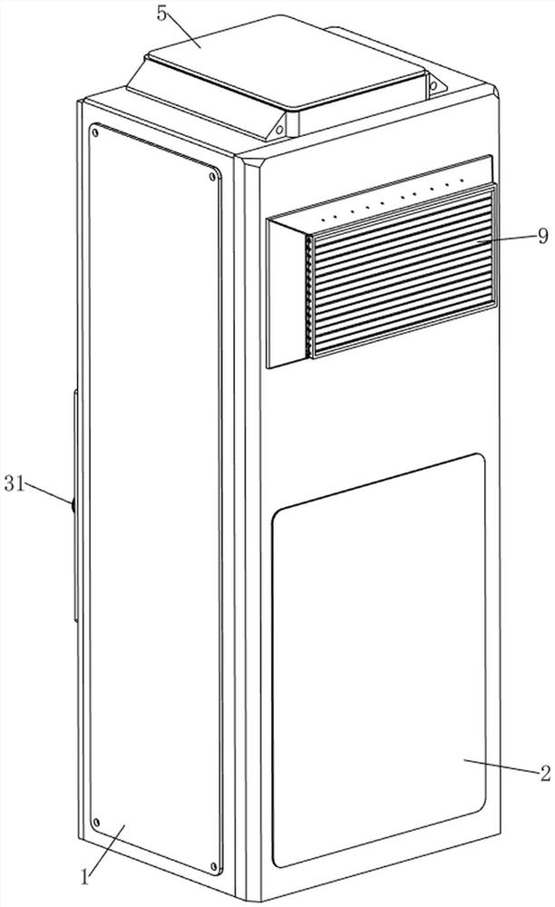
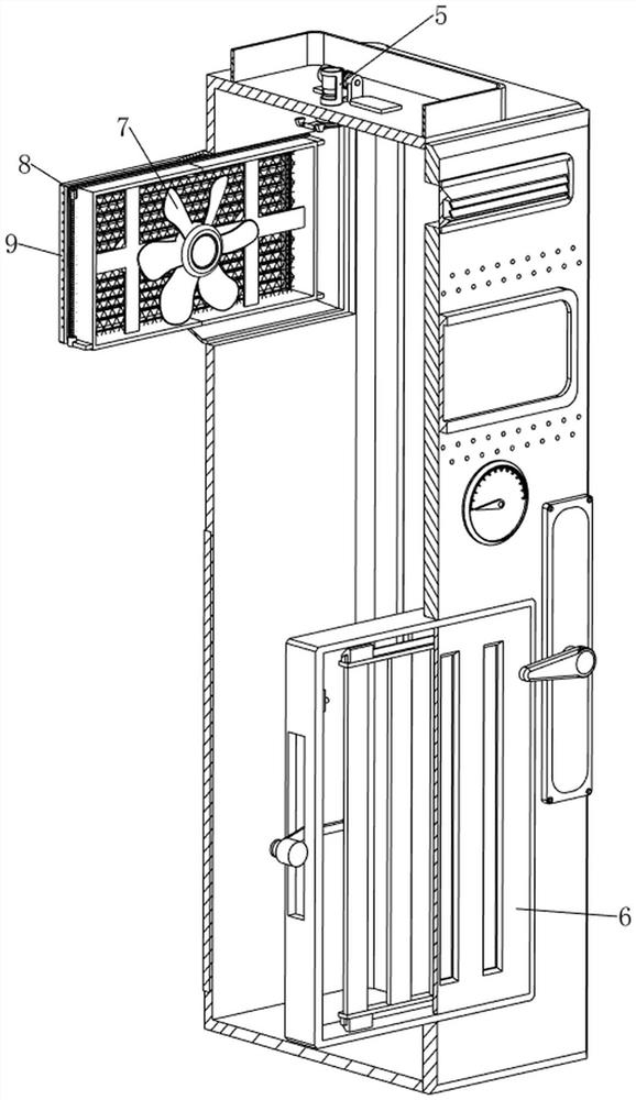
[0082] see figure 1 , figure 2 , image 3 and Figure 4 , a temperature control early warning device for high and low voltage equipment, comprising a cabinet 1, a revolving door 3, a revolving handle 31, a hot air blower 4, a detection mechanism 5, a ventilation mechanism 7 and a sliding mechanism 6, and the left front side of the cabinet 1 is hinged with a revolving door 3, Turning door 3 is used for closing cabinet 1, and turning door 3 front portion right lower side is connected with turning handle 31 in a rotating manner, and turning door 3 top is provided with hot air blower 4, and casing 1 top is provided with detection mechanism 5, and detection mechanism 5 is used for The internal temperature of the cabinet 1 is detected, and the lower side of the revolving door 3 is provided with a sliding mechanism 6. The sliding mechanism 6 facilitates the discharge of hot air inside the cabinet 1. The upper side of the rear of the cabinet 1 is provided with a ventilation mechani...

Embodiment 2

[0088] On the basis of Example 1, please refer to image 3 , Figure 11 and Figure 12 , also includes a cleaning mechanism 8, the cleaning mechanism 8 is used to clean the filter plate 74, the cleaning mechanism 8 includes a fixed block 81, a screw mandrel 82, a third reduction motor 83, a slider 84, a flat belt 85, and a wiping block 86 and the air flow sensor 87, the third fixed plate 72 inside the lower left side is welded with a fixed block 81, the third fixed plate 72 inside the right side is welded with a fixed block 81 symmetrically up and down, and the top of the fixed block 81 on the lower right side is fixed with a third Geared motor 83, the top of the fixed block 81 on the left side and the fixed block 81 on the upper right side are all connected with screw mandrel 82 through bearings, the bottom of the screw mandrel 82 on the right side is connected with the output shaft of the third geared motor 83 through a coupling A flat belt 85 is wound between the upper pa...


PUM


Abstract

The invention relates to an early warning device, in particular to a temperature control early warning device for high and low voltage equipment. The invention provides the high-low voltage equipment temperature control early warning device which does not need manual real-time monitoring. A temperature control early warning device for high and low voltage equipment comprises a case. The left front side of the case is rotationally connected with the rotating door; the right lower side of the front part of the rotating door is rotationally connected with the rotating handle; the air heater is arranged at the upper part of the rotating door; the top of the case is provided with the detection mechanism; the sliding mechanism is arranged on the lower side of the rotating door; and the ventilation mechanism is arranged on the upper side of the rear part of the case. According to the computer case, the temperature sensor is arranged, so that the temperature sensor can monitor the temperature in the case in real time, and therefore, the workload of workers can be reduced.

Description

technical field [0001] The invention relates to an early warning device, in particular to a temperature control early warning device for high and low voltage equipment. Background technique [0002] With the development of society, people pay more and more attention to the temperature detection inside the high and low voltage equipment. Because the high and low voltage equipment is closed and the internal space is small, people cannot find the circuit short circuit in time, which leads to accidents and huge losses. loss. [0003] The patent publication number is CN212849548U, which discloses a power distribution cabinet with heat dissipation function. The heat dissipation net is located on the left side outside the power distribution cabinet, and the heat dissipation net is fixedly connected to the power distribution cabinet. The top of the power distribution cabinet is provided with a heat dissipation box. , and the cooling box is fixedly connected to the power distributio...

Claims


Application Information

Patent Timeline
Patent Type & Authority Applications(China)
IPC IPC(8): H05K7/20H05K5/02B08B1/00
CPCH05K7/20H05K5/0217H05K5/0221H05K5/0213H05K7/20172H05K7/20181H05K7/20209B08B1/143
Inventor 彭世健王红军
Owner JIANGXI HJATIS POWER IND CO LTD
Learn More