Mounting mechanism for mounting sealing ring

An installation mechanism and sealing ring technology, applied in the mechanical field, can solve the problems of complex structure and low installation accuracy, and achieve the effect of simplifying the overall structure, reducing production costs and ensuring installation accuracy

Active Publication Date: 2022-04-22
浙江博民机电股份有限公司
View PDF6 Cites 0 Cited by
  • Summary
  • Abstract
  • Description
  • Claims
  • Application Information

AI Technical Summary

Problems solved by technology

[0004] The object of the present invention is to solve the above-mentioned problems existing in the prior art, and propose an installation mechanism for installing the sealing ring, which solves the problem of low installation accuracy and complex structure. The problem

Method used


Image

  • Mounting mechanism for mounting sealing ring
  • Mounting mechanism for mounting sealing ring
  • Mounting mechanism for mounting sealing ring

Examples


Embodiment 1

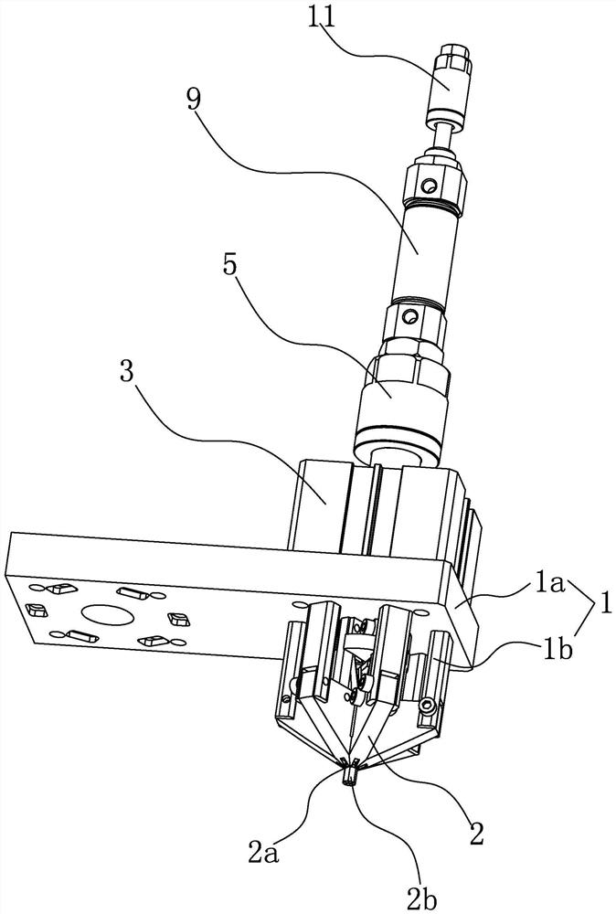
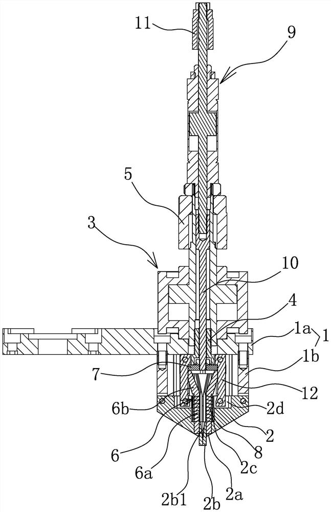
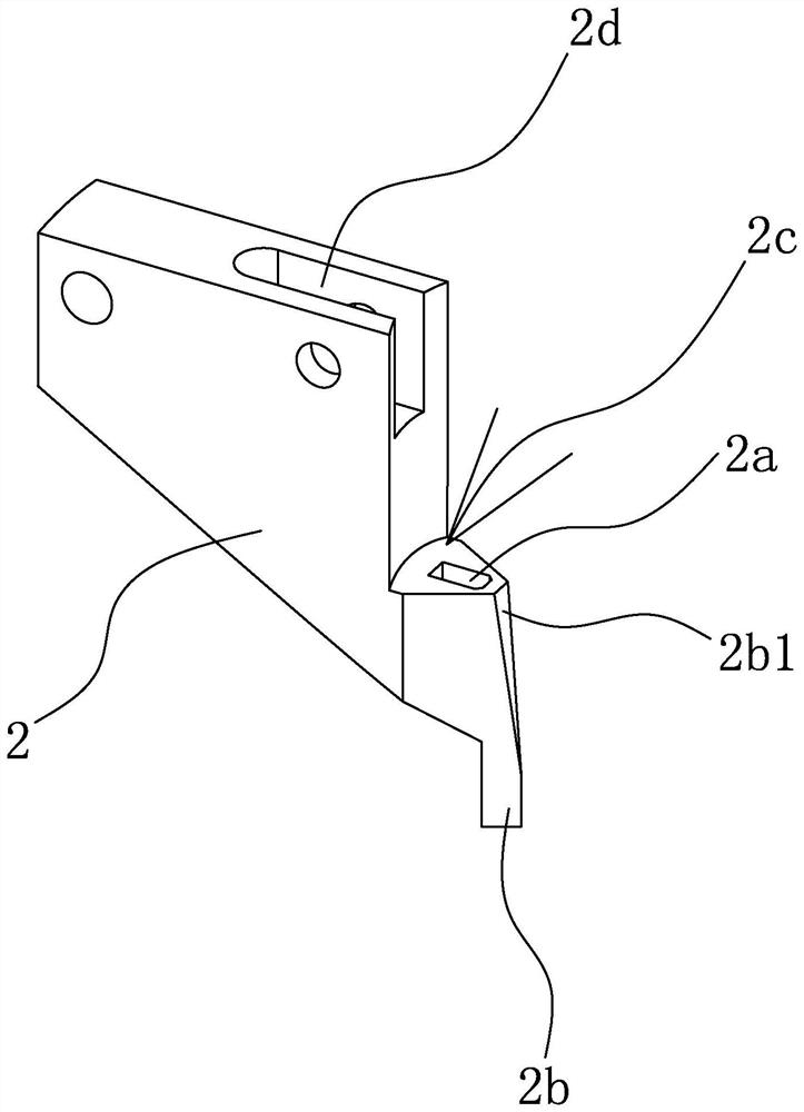
[0033] Such as figure 1 with figure 2 As shown, a mounting mechanism for installing a sealing ring includes a mounting base 1 and a number of support ring claws 2 connected to the lower side of the mounting base 1. Each support ring claw 2 is distributed along the circumferential direction and the lower end of each support ring claw 2 They can be gathered inwards or stretched outwards at the same time. Wherein, a support ring cylinder 3 is fixed on the upper side of the mounting seat 1, and the lower end of the piston rod of the support ring cylinder 3 is fixed with a coupling head 4 extending into the lower side of the mounting seat 1. Between the coupling head 4 and each support ring claw 2, there are Linkage structure, the upper end of the piston rod of the support ring cylinder 3 is threadedly connected with a spacer 5 that can abut against the upper end of the cylinder body of the support ring cylinder 3 when the piston rod of the support ring cylinder 3 moves downward....

Embodiment 2

[0038] The structure and principle of this embodiment are basically the same as that of Embodiment 1, the difference is that in this embodiment, the linkage structure includes a tapered block located at the lower end of the coupling head 4 and whose outer diameter gradually decreases from top to bottom, and a support ring claw 2 fixedly connected transmission rods, the upper end of the transmission rod abuts against the outer peripheral wall of the conical block and the support ring claw 2 is slidably connected with the mounting seat 1 along the radial direction of the conical block.


PUM


Abstract

The invention provides a mounting mechanism for mounting a sealing ring, and belongs to the technical field of machinery. The problems of low mounting precision and complex structure are solved. The ring expanding device comprises a mounting seat and a plurality of ring expanding claws connected to the lower side of the mounting seat, the ring expanding claws are distributed in the circumferential direction, the lower ends of the ring expanding claws can be gathered inwards at the same time or expanded outwards at the same time, and driving blocks which are located on the inner sides of the ring expanding claws and can move up and down are further arranged on the lower side of the mounting seat. A sliding groove is formed in the lower end of each ring supporting claw, stripping strips are arranged in the sliding grooves in a penetrating mode, each stripping strip is sleeved with a reset spring, and the stripping strips can move upwards under the action of the reset springs so that the lower ends of the stripping strips can retract into the sliding grooves. And when the driving block moves downwards, each stripping strip can be pushed to overcome the action of the reset spring and extend out of the sliding chute, so that the sealing ring supported by each ring supporting claw is downwards separated. The device has the advantages of high mounting precision, simple structure, low cost and the like.

Description

technical field [0001] The invention belongs to the technical field of machinery and relates to an installation mechanism for installing a sealing ring. Background technique [0002] The sealing ring is the most common sealing element, which is set between two parts to form a seal. Taking a valve as an example, a sealing ring needs to be set between the valve stem and the valve body for sealing. Traditionally, workers manually install the sealing ring to the corresponding parts (such as the valve stem), but this method is very inefficient and not suitable for automated production. In order to solve the above problems, the Chinese patent discloses an O-ring ring mechanism with the application number 201910335509.4, which includes a motor mounting plate, a working base plate is arranged on the top of the motor mounting plate, and several parallel distribution plates are arranged between the motor mounting plate and the working base plate. The supporting column of the motor mo...

Claims


Application Information

Patent Timeline
IPC IPC(8): B23P19/04B23P19/00
CPCB23P19/04B23P19/00
Inventor 郑志勇田保国胡齐峰张伟周兴良徐正家
Owner 浙江博民机电股份有限公司
Why Eureka
Try Eureka