Round pin-inserted positioning device and tensioning and positioning round pin thereof

A positioning device and plug-in technology, used in auxiliary devices, workpiece clamping devices, bolts, etc., can solve the problems affecting the matching accuracy of positioning holes, insufficient installation accuracy of accessories, and difficulty in online adjustment, so as to reduce product quality fluctuations and ensure Positioning accuracy and stability, the effect of improving production efficiency

Active Publication Date: 2011-07-13
GUANGQI HONDA
View PDF5 Cites 15 Cited by
  • Summary
  • Abstract
  • Description
  • Claims
  • Application Information

AI Technical Summary

Problems solved by technology

The resulting dimensional deviation will be transmitted to the installed accessories such as the door hinge, resulting in insufficient installation accuracy of the accessories, large fluctuations in fit, difficulty in online adjustment, and sometimes off-line repairs are required
In addition, when the positioning pin is mated with the positioning hole, it is directly inserted and pulled out. After repeated use, the positioning pin will be worn out, which will affect the accuracy of its cooperation with the positioning hole, and the installation accuracy of the door hinge and other accessories will require secondary adjustments after assembly. , affecting production efficiency
The fixture is usually removed during the second adjustment, and it is difficult to adjust the position of the door and the bolt with one hand.

Method used


Image

  • Round pin-inserted positioning device and tensioning and positioning round pin thereof
  • Round pin-inserted positioning device and tensioning and positioning round pin thereof
  • Round pin-inserted positioning device and tensioning and positioning round pin thereof

Examples


Embodiment Construction

[0022] The embodiments of the present invention will be described in detail below.

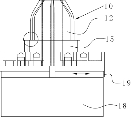
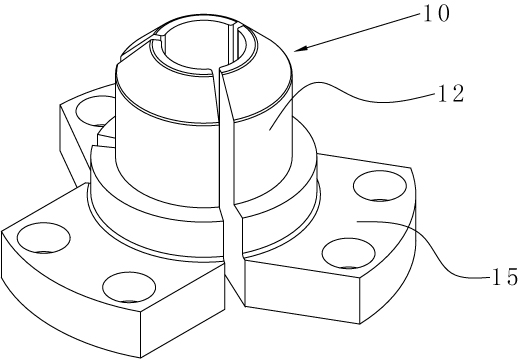
[0023] Such as figure 1 As shown, a tension positioning round pin 10 of the present invention has at least two lobes 12 separated from each other. Tension positioning round pin 10 is also called tension pin, or positioning pin. Close the pin flap 12 of the tension pin to shrink the tension pin 10, and the outer size of the tension pin 10 is smaller than the diameter of the positioning hole, so that it can be easily extended into the positioning hole, and then opened by the driving device The pin flap 12 of the tight pin makes the tension pin closely fit with the positioning hole. At this time, the outer size of the positioning pin 10 is equal to the diameter of the positioning hole, ensuring that there is no gap between the tension pin 10 and the positioning hole, improving the positioning accuracy and ensuring the fixture Positioning accuracy and stability to achieve precise positioning. Using...


PUM


Abstract

The invention discloses a tensioning and positioning round pin, which is provided with at least two pin flaps separated from each other, wherein when the pin flaps of the tensioning pin are folded, the tensioning pin contracts, so that the tensioning pin can easily extend into a positioning hole; and then, the tensioning pin is tightly combined with the positioning hole by unfolding the pin flapsof the tensioning pin, so that no gap exists between the tensioning pin and the positioning pin, the positioning accuracy and stability of a clamp are ensured, the installation accuracy of fittings such as a vehicle door hinge and the like is ensured, one-time installation success rate of a vehicle door is increased, the production efficiency is improved and the fluctuation of product quality is reduced. The invention also discloses a round pin-inserted positioning device. The round pin-inserted positioning device comprises the tensioning and positioning round pin provided with at least two pin flaps which are separated from each other, and an expansion device which is fixedly connected with the root parts of the pin flaps and drive the pin flaps to move along the radial direction. By adopting the round pin-inserted positioning device, the installation accuracy of the vehicle door hinge can be enhanced and the one-time installation success rate of the vehicle door can be increased.

Description

Technical field [0001] The invention relates to a tension positioning round pin. The invention also relates to a pin positioning device, in particular to a round pin insertion type positioning device. [0002] Background technique [0003] In the manufacturing industry, especially in automobile manufacturing, positioning pins are usually inserted into the positioning holes of the car body when installing car doors and other accessories. The positioning pins are round pins with a fixed diameter. The positioning pins and the positioning holes are clearance fits, such as positioning holes. When the diameter is 25mm, the diameter of the positioning pin is 24.7mm. The resulting dimensional deviation will be transmitted to the installed accessories such as door hinges, resulting in insufficient installation accuracy of the accessories, large fluctuations in the fit, and difficulty in online adjustment, sometimes requiring off-line repair. In addition, the positioning pin is directly...

Claims


Application Information

Patent Timeline
Patent Type & Authority Applications(China)
IPC IPC(8): F16B19/02B25B11/00B23K37/04
Inventor 王敏仲马建芳梁敏谦沈灿英
Owner GUANGQI HONDA
Why Eureka
Try Eureka