Optical cable quick connector for computer network engineering and use method thereof

A computer network and fast connection technology, which is applied in the direction of light guides, optics, optical components, etc., can solve the problem that the fixed ring is easy to spin and fall off, reduce the stability of the optical cable quick connector, and affect the normal use of the optical cable quick connector. Achieve the effect of improving connection stability, improving use stability, and ensuring normal use

Pending Publication Date: 2022-04-22
苏州多元网络工程有限公司
View PDF0 Cites 1 Cited by
  • Summary
  • Abstract
  • Description
  • Claims
  • Application Information

AI Technical Summary

Problems solved by technology

[0004] The purpose of the present invention is to provide a computer network engineering optical cable quick connector and its use method, to solve the problem that the existing optical cable quick connector proposed in the above background technology needs to be rotated and tightened on the two half-cylinders during use. The installation is realized on the threaded sleeve, but because the existing optical cable quick connector is not provided with any structure to prevent the fixing ring from falling off, the fixing ring is prone to spin and fall off later, which affects the normal use of the optical cable quick connector and reduces The use stability of the optical cable quick connector

Method used


Image

  • Optical cable quick connector for computer network engineering and use method thereof
  • Optical cable quick connector for computer network engineering and use method thereof
  • Optical cable quick connector for computer network engineering and use method thereof

Examples


Embodiment

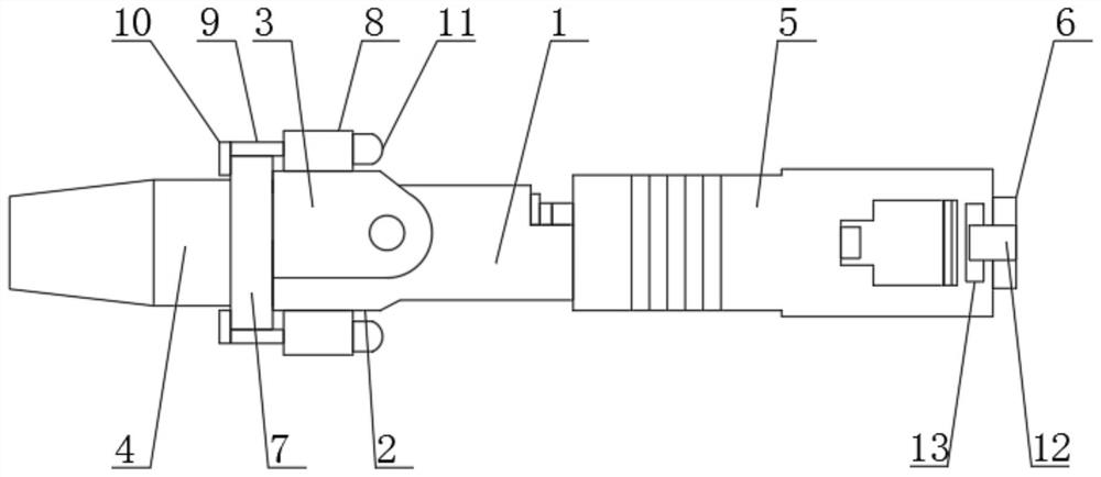
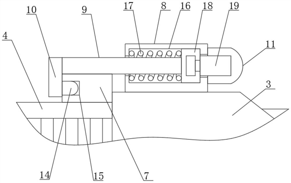
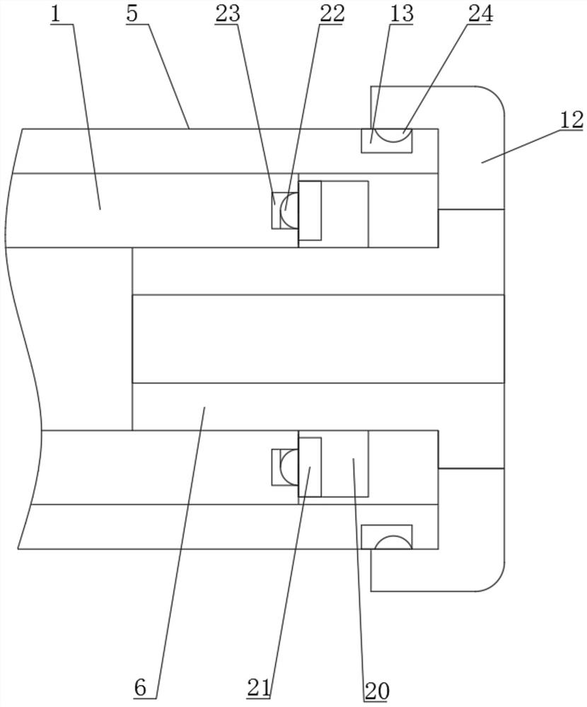
[0025] see Figure 1 to Figure 3 , the present invention provides a technical solution: an optical cable quick connector for computer network engineering, comprising a connector body 1, a fixing ring 4, a tail sleeve 5 and a dustproof cap 6, and one end of the connector body 1 is provided with an integrated The side seat 2, and the top of the side seat 2 is rotatably connected with a rotating sleeve 3, and the left side surfaces of the side seat 2 and the rotating sleeve 3 are provided with an integrated semi-cylindrical threaded sleeve, and the fixed ring 4 is screwed and sleeved on two semicircular On the barrel threaded sleeve, the top surface of the rotating sleeve 3 and the bottom surface of the side seat 2 are fixed with a rectangular block 8, and the inside of the rectangular block 8 is provided with a cylindrical inner groove 16, and the inner side of the cylindrical inner groove 16 is provided with a spring 17 and Circular inner block 18, the left side surface of circ...


PUM


Abstract

The invention discloses a quick optical cable connector for computer network engineering and a using method thereof.The quick optical cable connector comprises a connector body, a fixing ring, a tail sleeve and a dustproof cap, one end of the connector body is provided with an integrated side base, and the upper portion of the side base is rotationally connected with a rotating sleeve; the left side surface of the side seat and the left side surface of the rotating sleeve are each provided with an integrated semi-cylindrical threaded sleeve, the two semi-cylindrical threaded sleeves are sleeved with the fixing ring in a screwed mode, rectangular blocks are fixed to the top surface of the rotating sleeve and the bottom surface of the side seat, and cylindrical inner grooves are formed in the rectangular blocks; through the arrangement of the rectangular blocks, the side rods, the end blocks, the base rings, the limiting blocks, the annular limiting grooves and other structures, the fixing ring can be well prevented from falling off and limiting after being installed, the fixing ring is prevented from falling off in the subsequent use process, normal use of the quick optical cable connector is guaranteed, and the use stability of the quick optical cable connector is improved.

Description

technical field [0001] The invention belongs to the technical field of quick connectors for optical cables, in particular to a quick connector for optical cables used in computer network engineering and a method for using the same. Background technique [0002] In the process of connecting optical cables for computer network engineering, a quick connector for optical cables is required. This quick connector for optical cables is mainly composed of a connector body, a fixing ring, a tail sleeve and a dust cap. The rotating sleeve at the end of the main body is screwed up and opened, then the optical cable is inserted, and then the rotating sleeve is screwed down and closed, and fixed with a fixing ring, and finally the tail sleeve and the dust cap are installed to complete the connection of the optical cable quickly. [0003] When the existing optical cable quick connector is in use, the fixing ring needs to be rotated and tightened on the two semi-cylindrical threaded sleeve...

Claims


Application Information

Patent Timeline
Patent Type & Authority Applications(China)
IPC IPC(8): G02B6/38
CPCG02B6/381G02B6/3833G02B6/3849
Inventor 王明华
Owner 苏州多元网络工程有限公司
Why Eureka
Try Eureka